
Image: Maxwell's flywheel model of induction
Size of this preview: 253 × 600 pixels. Other resolution: 318 × 754 pixels.
Original image (318 × 754 pixels, file size: 26 KB, MIME type: image/png)
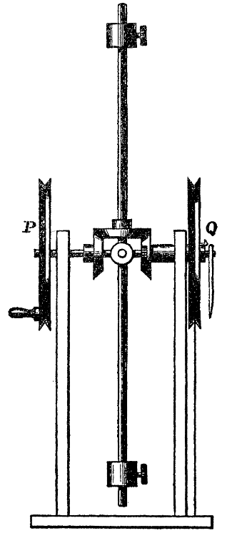
Description: Maxwell's differential gear model, c. 1876, used for the demonstration of electrical induction. The two outer flywheels P and Q represent the primary and secondary circuits; an increase of the moment of inertia of the flywheel in the middle illustrates the effect of placing an iron core between the two circuits. (From James Clerk Maxwell, A Treatise on Electricity and Magnetism, 3rd ed., Oxford, 1 1892, Vol. II, p. 228.)
Title: Maxwell's flywheel model of induction
Credit: James Clerk Maxwell, A Treatise on Electricity and Magnetism, 3rd ed., Oxford, 1 1892, Vol. 2, p. 228
Author: James Clerk Maxwell
Usage Terms: Public domain
License: Public domain
Attribution Required?: No
Image usage
The following page links to this image:

All content from Kiddle encyclopedia articles (including the article images and facts) can be freely used under Attribution-ShareAlike license, unless stated otherwise.