
Image: US1970 18410210 mannerofconstructingtheactionpartofpianofortes fig1

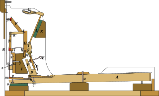
Description: From patent specification: A, Fig. 1, is the key, supported and moving on a fulcrum at a in the usual manner. B is the jack attached to the key. C is the fly or sticker operated by a spring D and a regulating screw E with its button F ; the same being constructed after the common method now generally in use. The foot of the hammer G is supported and turns on a pin b passing through the same and the two sides c, d, of a perpendicular stud H, secured to the cross rail I by a screw e. K, is a rail, having its face covered with cloth L, upon which the hammers fall and rest after striking the strings. The lower part or center block f, of the hammer, has a suitable notch g on which the fly or escapement of the grasshopper acts to throw the hammer forward. This notch g is shaped somewhat different from those of the common grasshopper action, inasmuch as it may be considered double, or consisting of the common projecting part d′, against which the fly bears to throw the hammer forward, and from or over which it is slipped or escapes and is received or abuts against a second projection c′, as the hammer retreats from the string. This latter projecting part c′ is so arranged that the hammer shall be permitted to fall back but a short distance from the string, immediately after the blow is given, or while the key is still held down by the finger of the performer. A very slight movement upward followed by a depression of the key, is thus sufficient to throw the hammer against the string and repeat its blow : so that a shake or trill can be most easily and effectually performed. A small wire spring M has one end inserted in the front of the center block f. That part of the spring near the end which is attached to the center block is turned around upon a cylinder two or three times into a circular form, as seen at h in the drawing, the remaining part extending to and bearing upon a projection i of an upright standard N supported on the rear end of the key lever A by means of a rod O, the foot of which rests thereon, the top of said rod being inserted in the bottom of the standard N as seen in Fig. 1. P is the damper extending diagonally from and attached to a cross piece Q, the latter being jointed to the top of each of the standards H and N or arranged so that it will move on pins k, l. While the hammer is at rest on the cloth L of the bar K, the damper remains in contact with the string R: but when the key A is depressed by the performer, the sticker or fly C being elevated, throws at that part of the center block f, in contiguity with it, and at the same time carries forward the hammer G, causing the same to strike upon the string R. As the foot of the rod O, of the standard N, rests on the top of the rear end of the key lever A, while the hammer is thrown forward, this rod is elevated and raises the end of the cross piece Q (to which it is jointed,) and the damper away from the string, the situation of the various parts being denoted in Fig. 1, by dotted lines. When the hammer strikes the string, and the escapement of the fly C in the notch g takes place, the force of the spring M is exerted to throw the hammer back and prevent its rebounding. The spring serves a treble purpose, and is one of the most important features of my improved action. It not only throws the hammer back upon the rest bar K, but by its action or pressure on the projection i it depresses the standard N, and consequently the end of the damper P, upon the strings, and also forces down the end of the key lever, upon which the rod O rests, and elevates the key end thereof. Thus it will be seen that the arrangement of the spring M, and the mode by which its power is applied to the adjacent parts, render the whole action exceedingly simple and efficient. The escapement of that part of the center block against which the end of the fly abuts, may be so arranged that the vibratory motion of the fly of the grasshopper may be very little in comparison with the same in other modes of action, thus abating almost entirely, if not rendering quite imperceptible, the noise occasioned by its return upon the button F. Furthermore the quick repetition or trilling of the hammers in piano notes can be most beautifully and easily effected when the keys are nearly down by a slight motion thereof. The arrangement of the action of common instruments, requires a great vibration of the keys to produce this operation. The rear end of the key lever has a piece of wood m, n, connected to it, or applied to its upper side. One end n is confined in any suitable manner, while the other is left free to be raised or depressed by a screw o, screwed through the end of the lever and abutting against the under side of the piece m, n, as seen in Fig. 1. The upper surface of the piece m, n, is covered with thin cloth or leather p, upon which the rod a rests. The object of the screw o is to regulate and insure the action of the damper P on the strings R. In order to adjust the height of the jack to the hammer, I affix the bottom part of the same upon a spring or piece of wood of a′ h′ Fig. 1, that has one end h′ properly secured by a screw, or otherwise, to the top of the hammer. The other end a′ being left free; I insert a screw c′ through the key on its underside, the end of which screw shall bear or abut against the lower side of the spring a′ h′. Therefore on turning up the screw, the spring and jack can be raised and vice versa, lowered by the action or spring of the wood. When it is desired to allow the strings a full vibration, while playing on the instrument, or in other words to remove the dampers entirely therefrom so that they may not strike the strings although the hammers do, they may be raised by placing the foot on a pedal which is suitably connected to and raises the damper rail S. This damper rail extends along under the projection i of the upright standard N, having a strip of cloth r fixed on its top upon which the under side of the projection i may be received when the damper rail is raised. Thus the elevation of the standard N, and cross bar or lever Q throws the end or cloth t of the dampers from the strings for the purpose above mentioned. The unichord action or change of the hammers and dampers from two strings to one is effected by a pedal so applied as to raise the end u, of a bent lever u v w Fig. 2. This lever has a fulcrum at v, and its end w rests against a pin or projection x, from the rail I, Figs. 1, and 2. The rails S, I, see Fig. 1, are connected by a screw y, which passes through a vertical elongated slot z cut through the former, and is screwed into the latter. The slot permits the damper rail S to be raised upward while when the slide rail I is moved laterally and so horizontally, when the pedal is raised by the pressure of the lever u v w on the projection x, the screw y bears against one side of the slot z and carries at the same time the damper rail with it. The strings are stretched diagonally as represented in Figs. 1, and 3 each hammer and damper bearing on two consecutive strings. Therefore when the hammers and dampers arc moved sidewise they leave one of the strings, and their action is confined to the other alone. Thus when the end u of the lever u v w is raised, the rail I, hammers and dampers are moved laterally and on removing the foot from the pedal, a spring T properly arranged throws back the same, thereby causing each of the hammers and dampers to act on two adjacent strings at every blow.
Title: US1970 18410210 mannerofconstructingtheactionpartofpianofortes fig1
Credit: Timothy Gilbert "Manner of constructing the Action part of Pianofortes" United States Patent no. 1,970 February 10, 1841
Author: Timothy Gilbert, traced and colorized by User:Mireut
Usage Terms: Public domain
License: Public domain
Attribution Required?: No
Image usage
The following page links to this image:
