
OR gate facts for kids
An OR gate is a basic building block in digital electronics. It's a type of logic gate that helps computers make decisions. Imagine it like a switch that turns on if at least one of its inputs is on.
In computer language, "on" is usually called "1" (or true), and "off" is called "0" (or false). So, an OR gate gives you a "1" output if any of its inputs are "1". If all its inputs are "0", then its output will also be "0".
A simple way to remember how an OR gate works is: "one or the other, or both."
| Input | Output | |
| A | B | A OR B |
| 0 | 0 | 0 |
| 0 | 1 | 1 |
| 1 | 0 | 1 |
| 1 | 1 | 1 |
How an OR Gate Works
An OR gate usually has two inputs and one output. It checks the status of its inputs. If input A is "1" OR input B is "1" (or both are "1"), the output will be "1". The only time the output is "0" is when both input A AND input B are "0".
This simple rule helps computers process information. OR gates are used in many electronic circuits to control how signals flow.
Symbols of the OR Gate
Engineers use special symbols to draw OR gates in circuit diagrams. There are three main symbols you might see:
 |
 |
 |
| MIL/ANSI Symbol | IEC Symbol | DIN Symbol |
- The MIL/ANSI Symbol is common in North America. It looks like a curved shield.
- The IEC Symbol is used internationally. It's a rectangle with a special shape inside.
- The DIN Symbol is another international standard, often seen in Europe.
Images for kids
-
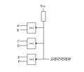
This image shows how an OR gate can be built using other types of logic gates.

See also
 In Spanish: Puerta OR para niños
