
Unified Modeling Language facts for kids
| Family | Modeling language |
|---|---|
The Unified Modeling Language (UML) is like a special drawing language for computers. It helps people create "blueprints" or maps for software and other systems. Think of it as a way to draw how a computer program will work before you even start writing the code.
UML uses different types of diagrams. These diagrams show how parts of a system connect. They also show how they behave and interact with each other. It's a visual way to plan and understand complex computer systems.
UML was created because many people wanted a standard way to design software. In the mid-1990s, some smart people like Grady Booch, James Rumbaugh, and Ivar Jacobson combined their ideas. They worked together to make one common language. The Object Management Group (OMG) later took over managing UML. In 1997, OMG made UML an official standard. This helped many companies use the same design language.
Most software developers use parts of UML. They often draw simpler diagrams by hand. But these drawings still use ideas from UML.
What is UML Used For?
UML is mostly used for making software. This includes programs for any industry. But it's also used in other areas.
For example, people use UML to:
- Plan business steps
- Show how system functions work
- Design database layouts
- Map out workflows in legal systems
- Plan medical electronics and healthcare systems
- Design computer hardware
UML works with many ways of developing software. It helps designers plan systems without being tied to a specific programming language. Some UML tools can even create computer code directly from a UML drawing!
Key Parts of UML Diagrams

UML diagrams help you see different parts of a system. They can show:
- Activities (like tasks or jobs)
- Components and how they work together
- The user interface (what you see on the screen)
- How the system actually runs
UML diagrams also let you add notes. These notes explain things like how to use a part of the system. They can also describe any rules or goals for that part.
Sharing UML Designs
UML designs can be shared between different UML tools. They use a special format called XML Metadata Interchange (XMI). This makes it easy for teams to work together.
What are Artifacts?

In UML, an "artifact" is a physical piece of information. It's something used or made during software creation. This can include models, source code, or even programs. It also covers tables in database systems, design documents, and email messages.
An artifact is the actual thing that gets put onto a node (like a computer server). Other UML parts, like classes, become artifacts first. Then, these artifacts are used in the system. Artifacts can also be made up of smaller artifacts.
How UML is Built (Metamodeling)

The OMG created a special way to define UML itself. It's called the Meta-Object Facility (MOF). Think of it as a set of layers.
- The top layer (M3) is like the language used to build the rules for UML.
- The next layer (M2) is the UML rulebook itself. It describes all the parts of UML.
- The M1 layer is where you create your actual UML drawings. These drawings follow the rules from the M2 layer.
- The bottom layer (M0) is the real system running. It's what your UML drawings describe.
This system allows UML to be very flexible. You can even add new features to UML using something called "stereotyping."
Types of UML Diagrams
UML 2 has many different types of diagrams. They are grouped into two main categories: structure diagrams and behavior diagrams.

Structure Diagrams
Structure diagrams show how the parts of a system are put together. They focus on objects, their features, and how they relate. These diagrams help document the software's design.
- Class diagram – Shows the structure of a class (a blueprint for objects).
- Component diagram – Shows how a software system is divided into parts. It also shows how these parts depend on each other.
- Composite structure diagram
- Deployment diagram
- Object diagram
- Package diagram
- Profile diagram
Behavior Diagrams
Behavior diagrams show what a system does. They show how objects work together and how their internal states change. These diagrams describe the system's functions.
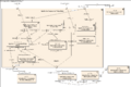
- Activity diagram – Shows the steps and actions in a process.
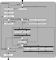
- State machine diagram – Shows the different states an object can be in. It also shows how it moves between these states.
- Use case diagram – Shows how a user interacts with a system.
Interaction Diagrams
Interaction diagrams are a special type of behavior diagram. They focus on how information and control flow between different parts of a system.
- Communication diagram – Shows how different parts talk to each other.
- Interaction overview diagram
- Sequence diagram – Shows interactions in the order they happen over time. Tools like Lucidchart and Draw.io can create these.
- Timing diagram – Focuses on when things happen and any time limits.
Examples of UML Diagrams
-
Component diagram
-

Class diagram
-
Activity diagram
-

Use case diagram
-
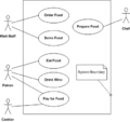
Use case diagram
-
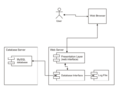
Deployment diagram


How Popular is UML?
UML was created to be a big help in software design. But it hasn't always been used as much as expected. Sometimes, people tried to use it for everything, which wasn't needed. Also, it was thought that anyone could design with it, but it takes skill.
UML is a very large language with many parts. Some people, like Ivar Jacobson, felt its size made it hard to learn. This might have slowed down its use. For example, Visual Studio stopped supporting UML in 2016 because not enough people were using it.
According to Google Trends, searches for "UML" have gone down since 2004. However, the interest has stayed steady in the last five years.
History of UML

UML started to develop in the late 1990s. It grew from earlier ways of designing software. These methods were created in the late 1980s and early 1990s. The image shows how UML and other design methods are connected over time.
How UML Began
In 1994, a company called Rational Software hired James Rumbaugh. He had created a popular design method called OMT. Rational Software already had Grady Booch, who had his own method. In 1995, Ivar Jacobson joined them. He was known for his OOSE method. These three "fathers of UML" worked to combine their ideas.
Early Versions: UML 1.x
UML was first based on the ideas from the Booch method, OMT, and object-oriented software engineering (OOSE). These were all brought together into one language. Rational Software led the development of UML from 1994 to 1996.
In 1996, a group called the UML Partners was formed. They wanted to finish the UML specification. They proposed UML 1.0 to the Object Management Group (OMG) in January 1997. Later that year, UML 1.1 was submitted and adopted by the OMG in November 1997. After this, several small updates were released, like versions 1.3, 1.4, and 1.5.
Modern Versions: UML 2
A major update, UML 2.0, replaced version 1.5 in 2005. This new version was made with a larger group of experts. They wanted to improve the language based on how people were using it.
While UML 2.1 was not a formal release, versions 2.1.1 and 2.1.2 came out in 2007. Then came UML 2.2 in 2009, UML 2.3 in 2010, and UML 2.4.1 in 2011. UML 2.5 was officially released in June 2015. The most recent formal version, 2.5.1, was adopted in December 2017.
UML 2.x has several parts:
- The Superstructure: This defines the look and meaning of diagrams.
- The Infrastructure: This is the core model that the Superstructure is built upon.
- The Object Constraint Language (OCL): This helps define rules for the model parts.
- The UML Diagram Interchange: This explains how UML 2 diagram layouts are shared.
Since version 2.5, the UML Specification has been simplified. It now combines the Superstructure and Infrastructure. The latest versions are UML Specification 2.5.1 and OCL version 2.4. Experts continue to update and improve UML.
See also
 In Spanish: Lenguaje unificado de modelado para niños
- Business Process Model and Notation
- C4 model
- Department of Defense Architecture Framework
- DOT (graph description language)
- List of Unified Modeling Language tools
- MODAF
- Model-based testing
- Model-driven engineering
- Modeling and Analysis of Real Time and Embedded systems
- Object-oriented role analysis and modeling
- Process Specification Language
- Systems Modeling Language
