
Atmel AVR facts for kids
The AVR is a special type of microcontroller. Think of it as a tiny computer chip that can control other electronic parts. It was created by a company called Atmel in 1996.
One cool thing about AVR chips is that they were among the first to have their program memory built right inside the chip. This memory, called flash memory, is where the instructions for the chip are stored. Before AVR, most microcontrollers used older, less convenient types of memory.
Many people believe that "AVR" stands for "Alf (Egil Bogen) and Vegard (Wollan)'s Risc processor." Alf and Vegard were the engineers who designed it.
The AVR design replaced an older type of microcontroller called MCS-51. The MCS-51 took 12 "clock cycles" (like tiny steps) to complete one main task. AVR microcontrollers can do most of their tasks in just one clock cycle! This means AVR chips are about 12 times faster for the same clock speed.
Inside the AVR chip, there are 32 special storage spots called "general purpose registers." These are directly connected to the part of the chip that does calculations (the ALU). This setup allows the chip to quickly grab two pieces of information and do a calculation with them in one go.
Contents
Basic Families
AVR microcontrollers come in different families, each designed for different needs.
tinyAVR
- Smallest family, good for simple tasks.
- Has 0.5 to 8 kilobytes (kB) of program memory.
- Up to 0.5 kB of SRAM (temporary memory).
- Up to 0.5 kB of EEPROM (another type of memory for saving data).
- Can run up to 20 megahertz (MHz), which is how fast it processes information.
- Comes in small packages with 6 to 32 pins.
megaAVR
- A medium-sized family, very popular and widely used.
- Has 4 to 256 kB of program memory.
- 0.5 to 16 kB of SRAM.
- 0.5 to 4 kB of EEPROM.
- Can run up to 20 MHz.
- Comes in packages with 20 to 100 pins.
XMEGA
- The most powerful family, designed for more complex projects.
- Has 16 to 384 kB of program memory.
- 2 to 32 kB of SRAM.
- Can connect to external memory (up to 16 megabytes of SRAM or SDRAM).
- 1 to 4 kB of EEPROM.
- Can run up to 32 MHz.
- Comes in packages with 44 to 100 pins.
Features
Every AVR chip has different features that help it connect to and control other electronics.
Input/Output Ports
AVR chips have "ports" which are groups of pins on the chip. Each pin can be set up to either receive information (input) or send information (output).
- If a pin is used for input, you can turn on a special "pull-up resistor" inside the chip. This helps make sure the signal is clear.
- If a pin is used for output, it can provide a small amount of power (up to 40 milliamps per pin, and 100 milliamps for all pins on a port).
A/D Converter
This is an "Analog-to-Digital converter." It takes signals from the real world (like temperature from a sensor, which is an analog signal) and turns them into numbers that the computer chip can understand (digital signals).
- tinyAVR and megaAVR chips usually have 10-bit converters, which can read signals from up to 8 different sources.
- XMEGA chips have more precise 12-bit converters, which can read signals from up to 16 different sources.
Timers/Counters
These are special parts of the chip that can keep track of time or count events. They can be used in different ways:
- PWM (Pulse Width Modulation): This is used to control things like the brightness of an LED or the speed of a motor. The timer rapidly switches a pin on and off, changing how long it stays "on" to control the power.
- Counter: This can count external events, like how many times a button is pressed or how many objects pass a sensor.
- Timer: This can create precise time delays or generate regular pulses, which is useful for making clocks or scheduling tasks.
TWI – Two Wire Interface
This is a way for the AVR chip to talk to other chips using only two wires. It uses the same rules as something called I2C.
UART/USART
This is another way for the AVR chip to communicate, often used to talk to computers or other devices using standards like RS232 or RS485.
SPI - Serial Peripheral Interface
This is a very fast way for the AVR chip to send and receive data from other devices. It's also used to put programs onto the chip's memory or read them back.
USI - Universal Serial Interface
This is a simpler way to transfer data using two or three wires.
JTAG
This is a special connection used by engineers to "debug" or find and fix problems in the program running on the chip.
D/A Converter
This is a "Digital-to-Analog converter." It does the opposite of the A/D converter: it takes numbers from the computer chip and turns them into real-world signals, like creating a specific voltage.
- Only XMEGA chips have this feature, usually with 12-bit precision and up to 2 channels.
Related pages
- Primary Sources
- , numerous AVR links
Images for kids
-
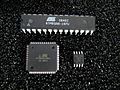
Various older AVR microcontrollers: ATmega8 in 28-pin narrow dual in-line package (DIP-28N), ATxmega128A1 in 100-pin thin quad flat pack (TQFP-100) package, ATtiny45 in 8-pin small outline (SO-8) package.
-
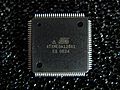
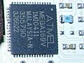
Atmel ATxmega128A1 in 100-pin TQFP package
-
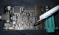
Atmel STK500 development board
-
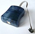
AVRISP mkII
-
AVR Dragon with ISP programming cable and attached, blue/greenish ZIF Socket
-
Atmel ATmega169 in 64-pad MLF package on the back of an Atmel AVR Butterfly board
-
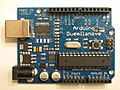
Atmel AVR ATmega328 28-pin DIP on an Arduino Duemilanove board
-
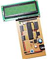
Atmel AVR ATmega8 28-pin DIP on a custom development board


See also
 In Spanish: AVR para niños
