Entity–relationship model facts for kids
An entity–relationship model (or ER model) is a way to describe how different pieces of information are connected. Think of it like a map for data. It helps us understand what information is important and how it relates to other information.

In computer science, ER models are often used to plan how information will be stored in a database. A database is like a super organized digital filing cabinet. For example, a business might use an ER model to figure out what details they need to remember about their customers, products, and sales.
Peter Chen created the ER model idea in 1976. Today, it's a common tool for students learning about how databases are built. It helps people design clear and organized ways to store data.
Contents
What is an ER Model?
An ER model helps us understand what data a business or system needs to keep track of. It shows the important "things" (called entities) and how they are connected (called relationships).
Imagine you're building a game. You'd need to keep track of players, characters, and items. An ER model would show:
- What information each player has (like their name).
- What information each character has (like their health).
- How players and characters are linked (a player owns a character).
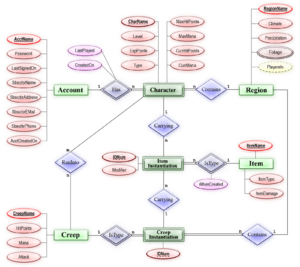
ER models are often drawn as diagrams. Boxes show the entities, and lines connect them to show relationships. For example: one building can have many apartments, but one apartment is only in one building.
Entities and Attributes
An entity is a "thing" that can exist on its own and that we want to store information about. It could be a real object, like a car, or an idea, like a customer order.
Think of entities as nouns. Examples include:
- A computer
- An employee
- A song
- A student
Entities have attributes. Attributes are like facts or details about an entity. They describe the entity.
- An employee entity might have attributes like name, address, or phone number.
- A song entity might have attributes like title or artist.
One special attribute is the "primary key." This is a unique identifier for each entity. For example, a student ID number is a primary key because every student has a different one.
Relationships
A relationship shows how two or more entities are connected. Think of relationships as verbs. They describe the action or link between entities.
- A company owns a computer.
- An artist performs a song.
- A student enrolls in a course.
Relationships can also have attributes. For example, a "performs" relationship between an artist and a song might have a "date" attribute, showing when the song was performed.
How ER Models Become Databases
An ER model is usually turned into a database. In a simple database, each entity type becomes a table. Each row in the table is one instance of an entity. Each column in the table is an attribute.
For example, an "Employee" entity would become an "Employees" table. Each row would be a different employee, and columns would be "Name," "Address," and "Phone Number."
Relationships between entities are made by linking tables. This is often done using primary keys and "foreign keys." A foreign key is a primary key from one table that is stored in another table to show a connection.
Levels of ER Models
ER models can be built at different levels of detail. This helps in planning large systems.
- Conceptual data model
- This is the highest level. It shows the main ideas and connections without much detail. It's like a big picture map of all the important data an organization uses. It helps everyone agree on the basic information.
- Logical data model
- This model adds more detail than the conceptual model. It defines all the entities and their attributes, and how they relate. However, it doesn't worry about the specific type of database software that will be used. It's like a detailed blueprint for the data, but not yet tied to a specific building material.
- Physical data model
- This is the most detailed model. It's designed for a specific database system. It includes all the technical details needed to actually build the database, like table names, column types, and how data will be indexed for faster searching. It's the final plan ready for construction.
These models help designers plan information systems. They start with the big picture (conceptual), then add more detail (logical), and finally create the exact plan for the database (physical).
Drawing ER Diagrams
ER diagrams use special shapes to show entities, relationships, and attributes.
- Rectangles usually show entity sets (like "all students").
- Diamonds show relationship sets (like "all enrollments").
- Ovals show attributes (like "student name").
Lines connect these shapes. Sometimes, attributes are listed inside the entity rectangles to keep the diagram cleaner.
Cardinality: How Many?
Cardinality rules show how many instances of one entity can relate to how many instances of another entity. It's like saying "one-to-one," "one-to-many," or "many-to-many."
For example, a "student" can enroll in "many courses" (one-to-many). But a "course" can have "many students" (many-to-many).

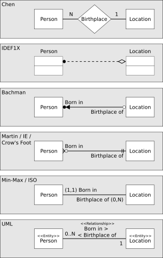
Different ways of drawing ER diagrams use different symbols for cardinality.
Crow's Foot Notation
One popular way to draw ER diagrams is called "Crow's Foot notation." It uses specific symbols at the ends of the lines that connect entities.
- A ring (circle) means "zero."
- A dash (straight line) means "one."
- A crow's foot (three lines like a bird's foot) means "many."
These symbols are used in pairs to show the minimum and maximum number of connections:
- Ring and dash (O—): Zero or one (optional). Example: A student may have a locker (0 or 1).
- Dash and dash (— —): Exactly one (mandatory). Example: A student must have one student ID (exactly 1).
- Ring and crow's foot (O<): Zero or many (optional). Example: A teacher can teach zero or many classes.
- Dash and crow's foot (—<): One or many (mandatory). Example: A class must have one or many students.
Crow's Foot notation is widely used because it's clear and easy to understand for many people.
See also
 In Spanish: Modelo entidad-relación para niños
- Database design
- Data structure diagram
- UML class diagrams
 | Misty Copeland |
 | Raven Wilkinson |
 | Debra Austin |
 | Aesha Ash |


