
Phase-shift keying facts for kids
Phase shift keying (PSK) is a clever way to send information using radio waves. Imagine a radio wave as a wiggly line, like a sine wave. PSK works by changing the 'phase' of this wave. The phase is like where the wave is in its wiggle at a certain moment. This change in phase carries all the secret messages! It helps us send more data using less radio space.

Contents
What is a Phase Shift?
Think of a wave as a continuous up-and-down wiggle. It moves a certain number of times each second. A 'phase shift' happens when we suddenly change where the wave is in its wiggle. For example, if the wave is at the very top of its wiggle, we could instantly make it jump to the very bottom. This sudden change is a phase shift. We use these changes to send information.
How PSK Sends Information
We can send information by either changing the wave's phase or not changing it. This happens every time the wave reaches a specific point, like the top of its wiggle.
Binary Phase Shift Keying (BPSK)
One simple type is called Binary Phase Shift Keying, or BPSK. 'Binary' means it uses two options, like 0 and 1.
- If we change the wave's phase when it reaches the top, this can mean we are sending a '1'.
- If we do not change the wave's phase, this can mean we are sending a '0'.
Computers and radios work together to do this. A computer can turn text or other data into a series of 1s and 0s. A radio then uses BPSK to turn these 1s and 0s into changes in a radio wave. Another radio and computer listening can then figure out the original message. They listen for the phase changes (or lack of them) to turn the wave back into 1s and 0s, and then back into text.
Where is PSK Used?
Binary Phase Shift Keying is a very good way to send computer data using radio waves. It is used in many modern communication systems. Some Wireless LAN (Wi-Fi) standards use Phase-shift keying. They sometimes combine it with another method called Orthogonal frequency-division multiplexing (OFDM). This combination helps them send data even faster.
Images for kids
-
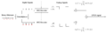
Conceptual transmitter structure for QPSK. The binary data stream is split into the in-phase and quadrature-phase components. These are then separately modulated onto two orthogonal basis functions. In this implementation, two sinusoids are used. Afterwards, the two signals are superimposed, and the resulting signal is the QPSK signal. Note the use of polar non-return-to-zero encoding. These encoders can be placed before for binary data source, but have been placed after to illustrate the conceptual difference between digital and analog signals involved with digital modulation.
-
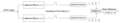
Receiver structure for QPSK. The matched filters can be replaced with correlators. Each detection device uses a reference threshold value to determine whether a 1 or 0 is detected.
-
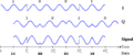
Timing diagram for offset-QPSK. The binary data stream is shown beneath the time axis. The two signal components with their bit assignments are shown the top and the total, combined signal at the bottom. Note the half-period offset between the two signal components.
-
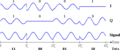
Timing diagram for π/4-QPSK. The binary data stream is shown beneath the time axis. The two signal components with their bit assignments are shown the top and the total, combined signal at the bottom. Note that successive symbols are taken alternately from the two constellations, starting with the "blue" one.
-
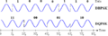
Timing diagram for DBPSK and DQPSK. The binary data stream is above the DBPSK signal. The individual bits of the DBPSK signal are grouped into pairs for the DQPSK signal, which only changes every Ts = 2Tb.
-

Differential encoding/decoding system diagram


See also
 In Spanish: Modulación por desplazamiento de fase para niños
