
Backstaff facts for kids
The backstaff was a special tool sailors used long ago to figure out where they were. It helped them measure how high the Sun or Moon was in the sky. When using it for the Sun, sailors would stand with their back to the Sun (that's why it's called a backstaff!). They would look at the shadow the tool made. An English sailor named John Davis invented it in 1594 and wrote about it in his book Seaman's Secrets.
Contents
Different Kinds of Backstaffs
A backstaff is any tool that measures the Sun's height using its shadow. The idea of looking backward at the Sun to measure its height might have come from Thomas Harriot. Many tools that developed from the cross-staff can be called backstaffs. But the Davis quadrant was by far the most important one in the history of sailing tools. In fact, when people say "backstaff," they usually mean the Davis quadrant. However, John Davis wasn't the only one to design such a tool, and we'll look at some others too.
The Davis Quadrant

Captain John Davis created his version of the backstaff in 1594. Davis was a skilled sailor who knew a lot about the tools of his time, like the mariner's astrolabe, the quadrant, and the cross-staff. He saw the problems with these tools and wanted to make a new one that was easier and more accurate for measuring the Sun's height.
One early design of his quadrant staff is shown in Figure 1 (in the gallery below). It had a curved piece (called an arc) attached to a long stick. This arc (A) would cast its shadow onto a "horizon vane" (B). The sailor would look along the stick and see the horizon through a small slit in the horizon vane. By sliding the arc until its shadow lined up with the horizon, the angle of the Sun could be read from the stick. This was a simple quadrant, but it wasn't as precise as sailors needed. Its accuracy depended on how long the stick was, but a very long stick made the tool hard to handle. This early tool could only measure angles up to 45 degrees.
The next version of his quadrant is shown in Figure 2. The arc at the top was replaced with a "shadow vane" placed on a movable bar. This bar could slide along a marked scale to show the angle of the shadow. Below the stick, a 30-degree arc was added. The sailor would look through the "horizon vane" on the left and line up the horizon with the shadow. A "sighting vane" on the arc was moved until it lined up with the horizon view. The total angle was found by adding the angle from the movable bar and the angle from the arc.
The tool that most people now know as the Davis quadrant is shown in Figure 3. This design became common by the mid-1600s. The main arc was split into two parts. A smaller, 60-degree arc was placed above the stick. A larger, 30-degree arc was placed below. Both arcs shared a central point. At this center, a "horizon vane" with a slit (B) was placed. A movable "shadow vane" was put on the upper arc so its shadow fell on the horizon vane. A movable "sight vane" was placed on the lower arc (C).
It's easier for a person to place a vane at a specific spot than to read an arc at a random position. This is because our eyes are good at lining up two lines accurately. So, a small arc with fewer marks could be used to place the shadow vane precisely. On the other hand, moving the sight vane to where the horizon meets the shadow needs a large arc. This is because the exact spot might be a tiny fraction of a degree, and a large arc helps you read smaller marks more accurately. Later versions of the large arc even had special lines called transversals to allow for even more precise readings.
This clever design allowed Davis to make a quadrant that was both small and large at the same time, giving the accuracy of a big tool without being too bulky. This type of tool became known as the backstaff. It was one of the most popular backstaffs used by sailors. Sailors in other European countries even called it the English Quadrant.
Later, a change was made to the Davis quadrant: a "Flamsteed glass" was used instead of the shadow vane. This was suggested by John Flamsteed. This glass was a lens that projected an image of the Sun onto the horizon vane instead of just a shadow. This was helpful when the sky was hazy or slightly cloudy, as the faint image of the Sun could be seen more clearly on the horizon vane when a shadow might not appear.
-
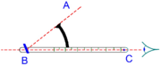
Figure 1 – An early version of the Davis Quadrant, from his book Seaman's Secrets. It could only measure angles up to 45 degrees.
-
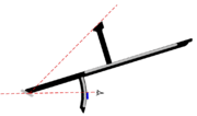
Figure 2 – The second Davis Quadrant, also from Seaman's Secrets. The arc above was replaced with an arc below and a shadow-casting bar above. This tool could measure up to 90 degrees.
-
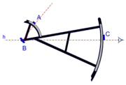
Figure 3 – The Davis Quadrant as it looked by the mid-1600s. The upper bar was replaced with a 60-degree arc.


How to Use a Davis Quadrant
To use the Davis quadrant, a sailor would first guess the Sun's height and set the shadow vane to that angle. Holding the tool in front of them, with their back to the Sun, they would hold it so the shadow from the shadow vane fell exactly on the horizon vane, next to a small slit. Then, they would move the sight vane until they could see the horizon through the sight vane and the horizon vane's slit. At the same time, they had to keep the shadow in place. This allowed them to measure the angle between the horizon and the Sun by adding the angles read from the two arcs.
Since the edge of the shadow shows the edge of the Sun, the sailor had to make a small adjustment to the reading for the Sun's size.
Tools Based on the Davis Quadrant
The Elton's quadrant was a tool that came from the Davis quadrant. It added a special arm with spirit levels to create an "artificial horizon," which was helpful when the real horizon wasn't clear.
The Demi-Cross

The demi-cross was another tool used at the same time as the Davis quadrant. It was quite popular outside of England.
It had a vertical bar, like half of the bar on a cross-staff, which is why it was called "demi-cross" (demi means half). This bar held a "shadow vane" (A in Figure 4) that could be set at different heights. By changing the shadow vane's height, the range of angles that could be measured was set. The bar could slide along the main stick, and the angle was read from one of the scales on the stick.
The "sight vane" (C) and "horizon vane" (B) were lined up by eye with the horizon. When the shadow from the shadow vane fell on the horizon vane and lined up with the horizon, the angle was known. In practice, this tool was accurate but harder to handle than the Davis quadrant.
The Plough Instrument

The plough was the name given to a unique tool that was only used for a short time. It was a mix between a cross-staff and a backstaff. In Figure 5, 'A' is the bar that casts its shadow on the horizon vane at 'B'. This works like the stick in Figure 1. 'C' is the sighting vane. The sailor uses the sighting vane and the horizon vane to make sure the tool is level. The sighting vane can move left and right along the stick. 'D' is another bar, just like you'd find on a cross-staff. This bar has two vanes that can be moved closer or farther from the stick to act like bars of different lengths. This bar could also be moved on the stick and used to measure angles.
Almucantar Staff
The Almucantar staff was a tool used especially for measuring the Sun's height when it was very low in the sky.
Cross-Staff
The cross-staff was usually used for direct observations (looking straight at the Sun). However, later on, it was changed so it could also be used for back observations.
Back Observation Quadrant
There was a special kind of quadrant – the Back observation quadrant – that was used to measure the Sun's height by looking at the shadow it cast on a horizon vane.
Thomas Hood Cross-Staff

Thomas Hood invented this cross-staff in 1590. It could be used for land surveying, studying the stars, or other geometry problems.
It has two main parts: a vertical bar (transom) and a horizontal bar (yard). The transom is marked from 0 degrees at the top to 45 degrees at the bottom. At the top of the transom, a vane is placed to cast a shadow. The yard is horizontal and marked from 45 degrees to 90 degrees. The transom and yard are connected by a special part (the "double socket" in Figure 6) that lets them move separately.
It was also possible to build the tool with the yard at the top of the transom instead of the bottom.
To use it, the transom and yard are first set so they meet at their 45-degree marks. The tool is held so the yard is level (the sailor can look along the yard to help with this). The socket is loosened, and the transom is moved up or down until the shadow of the vane falls on the 90-degree mark of the yard. If moving only the transom works, the height is read from the transom's marks. If the Sun is too high for this, the yard's horizontal opening is loosened, and the yard is moved to make the shadow land on the 90-degree mark. The yard then gives the height.
This was a fairly accurate tool because its marks were well spaced out compared to a regular cross-staff. However, it was a bit clumsy and hard to use in windy conditions.
Benjamin Cole Quadrant

This tool was a later addition to the world of backstaffs, invented by Benjamin Cole in 1748.
The tool has a main stick with a pivoting quadrant at one end. The quadrant has a "shadow vane" (A in Figure 7) at the top of its marked scale. This vane could also have a lens, like the Flamsteed glass on the Davis quadrant, to project an image of the Sun. This shadow or image falls on the "horizon vane" (B). The person using it looks at the horizon through a hole in the "sight vane" (D) and a slit in the horizon vane to make sure the tool is level. The quadrant part is rotated until the horizon and the Sun's image or shadow are perfectly lined up. The Sun's height can then be read from the quadrant's scale. To get an even more precise reading, a circular vernier is attached to the stick (C).
The fact that such a tool was still being introduced in the mid-1700s shows that the quadrant was still a useful tool, even though the octant (a newer, more advanced tool) was also available.
An English scientist named George Adams created a very similar backstaff at the same time. Adam's version made sure that the distance between the Flamsteed glass and the horizon vane was the same as the distance from the vane to the sight vane.
Cross Bow Quadrant

Edmund Gunter invented the cross bow quadrant, also called the mariner's bow, around 1623. It got its name because it looked a bit like an archer's crossbow.
This tool is interesting because its arc is actually 120 degrees long, but it's only marked as a 90-degree arc. This means that each degree mark on the arc is slightly wider than a true degree. You can find examples of this tool with marks from 0 to 90 degrees, or with two mirrored 0 to 45-degree sections centered on the middle of the arc.
The tool has three vanes: a "horizon vane" (A in Figure 8) with an opening to see the horizon, a "shadow vane" (B) to cast a shadow on the horizon vane, and a "sighting vane" (C) that the sailor uses to look at the horizon and the shadow on the horizon vane. This helps make sure the tool is level while also measuring the Sun's height. The height is found by calculating the difference between the angles of the shadow and sighting vanes.
Some versions of this tool even had the Sun's declination (its angle north or south of the equator) marked on the arc for each day of the year. This allowed the sailor to set the shadow vane to the current date, and the tool would directly show the Sun's height.
