Circuit diagram facts for kids
A circuit diagram is like a map for electrical circuits. It uses special pictures and symbols to show how electronic parts are connected. You might also hear it called an electrical diagram or electronic schematic.
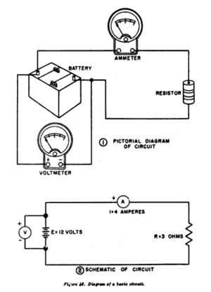
There are two main types. A pictorial circuit diagram uses simple drawings of the actual parts. A schematic diagram uses standard symbols to represent each part. These diagrams help people design, build, and fix electronic devices. For example, they are used to create PCBs, which are the green boards inside many gadgets. In computer science, circuit diagrams can even help understand how Boolean algebra works.
Contents
Symbols in Circuit Diagrams
Circuit diagrams use special symbols for each electrical part. Think of them like an alphabet for electronics. These symbols have changed over time and varied between countries. But now, many of them are the same all over the world.
For example, the symbol for a resistor is often a simple rectangle. Sometimes, the value of the resistor in ohms is written inside it. These symbols make it easy for anyone who understands them to read a circuit diagram.
How Circuit Diagrams Are Organized
Most circuit diagrams are organized in a special way. They usually flow from left to right and from top to bottom. This helps you follow the path of the main signal or power.
Imagine a diagram for a radio. The antenna input, where the signal comes in, would be on the left. The loudspeaker, where the sound comes out, would be on the right. This layout makes it easier to understand how the circuit works step by step. There are international rules for making these diagrams, set by the IEC.
From Diagram to Real Circuit
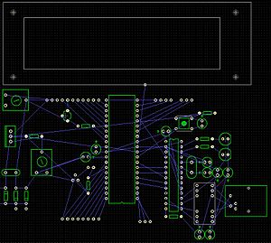
Once a circuit diagram is complete, it's used to create a physical circuit. This often means making a printed circuit board (PCB). The first step is called "schematic capture." This is where the diagram is turned into a digital plan.
The digital plan often looks like a "rat's nest." This is a jumble of lines showing where all the wires need to connect. Then, special computer programs help arrange the parts and find the best paths for the connections. This process creates the final design for the integrated circuit or PCB. It's how the ideas from the diagram become real electronic parts.
See also
 In Spanish: Diagrama electrónico para niños


