
Spanning Tree Protocol facts for kids
The Spanning Tree Protocol (STP) is a special set of rules for computer networks. It helps prevent problems when you have extra connections between network devices like switches. Think of it like a traffic cop for your network, making sure data doesn't get stuck in endless loops. STP also allows you to have backup connections, so if one link fails, your network can still work.
STP creates a "spanning tree" in your network. This means it finds the best path for data to travel between any two points and temporarily turns off any extra paths that could cause trouble. This idea was first thought up by Radia Perlman while she was working at Digital Equipment Corporation.
Later, in 2001, a faster version called Rapid Spanning Tree Protocol (RSTP) was introduced. RSTP helps networks recover much quicker if a connection breaks. Both STP and RSTP are part of the IEEE standards, which are like rulebooks for technology.
Contents
How Spanning Tree Protocol Works


Imagine you have many switches in your local area network (LAN). Sometimes, people connect these switches with extra cables. This is good because if one cable breaks, you have a backup. But these extra cables can also create "loops."
Why Network Loops are Bad
If a loop forms, data can endlessly circle around the network. This causes a "broadcast storm," where too much data floods the network, making it slow or even crash. It can also confuse switches about where devices are located.
How STP Stops Loops
To stop these problems, STP runs on your switches. It constantly checks the network map. When it finds extra connections that could cause a loop, it "blocks" them. This means it turns off the forwarding of data on those specific links.
STP chooses one main switch to be the "root bridge." All other switches then find the best way to connect to this root bridge. They use this best path for all data. If that main path ever fails, STP quickly turns on one of the blocked backup links.
Finding the Best Path
Switches talk to each other using special messages called bridge protocol data units (BPDUs). These messages help them figure out the network layout.
The root bridge calculates the "cost" of each path based on how fast the connection is (its bandwidth). A faster connection has a lower cost. STP always picks the path with the lowest cost as the main path.
Other switches also figure out their best path to the root bridge. They add up the costs of all the connections along a path. The path with the lowest total cost becomes their main way to reach the root bridge.
Path Cost Values
The cost of a path depends on the speed of the network link. Faster links have lower costs, meaning they are preferred.
| Data rate (link bandwidth) |
Original STP cost (802.1D-1998) |
RSTP/MSTP cost (recommended value) |
|---|---|---|
| 4 Mbit/s | 250 | 5,000,000 |
| 10 Mbit/s | 100 | 2,000,000 |
| 16 Mbit/s | 62 | 1,250,000 |
| 100 Mbit/s | 19 | 200,000 |
| 1 Gbit/s | 4 | 20,000 |
| 2 Gbit/s | 3 | 10,000 |
| 10 Gbit/s | 2 | 2,000 |
| 100 Gbit/s | N/A | 200 |
| 1 Tbit/s | N/A | 20 |
Port States
When a device connects to a switch port, it doesn't immediately start sending data. The port goes through different states to make sure it won't cause a loop:
- Blocking: The port is not sending or receiving data, but it listens for STP messages. This state prevents loops.
- Listening: The port processes STP messages to figure out the network map.
- Learning: The port learns the MAC addresses of devices connected to it, but still doesn't send user data.
- Forwarding: The port is fully active and sending/receiving data. This is the normal state for a working connection.
If a computer or printer connects to a switch, its port will usually go into the forwarding state after a short delay (about 30 seconds). If another switch connects, the port might stay in blocking mode if it would create a loop.
Setting Up Spanning Tree Protocol
Setting up STP means planning your network carefully. You need to turn on STP on all your switches and make sure they use the same version of the protocol.
Choosing the Root Bridge
Network administrators can choose which switch will be the root bridge. This is usually the most powerful or central switch. If the chosen root bridge ever goes offline, STP will automatically pick a new one.
The root bridge is chosen based on its "bridge ID." This ID is a combination of a priority number and the switch's unique MAC address. The switch with the lowest bridge ID becomes the root bridge. If two switches have the same priority, the one with the lowest MAC address wins.

How Paths are Chosen
After the root bridge is picked, other switches decide their best path to it. They look at:
- The lowest root bridge ID (this picks the root bridge).
- The lowest cost to the root bridge (this favors faster connections).
- The lowest sender bridge ID (a tiebreaker if costs are equal).
- The lowest sender port ID (another tiebreaker if a switch has multiple links to the same upstream switch).

Bridge Protocol Data Units (BPDUs)
BPDUs are like special messages that switches send to each other to share information about the network. They help switches figure out who the root bridge is and which ports should be active or blocked.
Switches send BPDUs using their unique port address. These messages are sent to a special address that all STP-enabled devices listen to.
There are two main types of BPDUs in the original STP:
- Configuration BPDU: Used to figure out the spanning tree.
- Topology Change Notification (TCN) BPDU: Used to tell other switches when something changes in the network, like a cable breaking or a new device connecting.
BPDUs are sent regularly (every 2 seconds by default). This helps switches quickly adapt to network changes.
Rapid Spanning Tree Protocol (RSTP)
As networks grew, the original STP was sometimes too slow to react to changes. So, in 2001, the Rapid Spanning Tree Protocol (RSTP) was created. RSTP is much faster at recovering from network changes or failures. While STP could take 30-50 seconds, RSTP can often react in just a few seconds or even milliseconds.
New Roles for Ports in RSTP
RSTP adds new roles for switch ports to speed things up:
- Root: The best path from a non-root switch to the root bridge.
- Designated: The main forwarding port for a network segment.
- Alternate: A backup path to the root bridge, different from the root port.
- Backup: A backup path to a segment where another port is already connected.
- Disabled: A port that has been manually turned off by a network administrator.
Faster Operation of RSTP
RSTP makes things faster by:
- Detecting root switch failures in just 6 seconds (by default).
- Allowing "edge ports" (ports connected to end devices like computers) to go directly to the forwarding state without delay.
- Using a "handshake" process between switches to quickly transition ports to forwarding. This means switches can agree on the best path much faster.
- Keeping backup information about blocked ports, so they can be activated quickly if needed.
Spanning Tree for VLANs
In modern networks, switches often divide the network into smaller virtual networks called VLAN. STP and RSTP usually treat the whole network as one. However, it's often useful to have separate spanning trees for different VLANs. This allows traffic for different VLANs to use different paths, making the network more efficient.
Multiple Spanning Tree Protocol (MSTP)
The Multiple Spanning Tree Protocol (MSTP) is an extension to RSTP. It lets you create multiple spanning trees, where each tree can include one or more VLANs. This means you can group VLANs together and apply a specific spanning tree to that group.
MSTP is smart because it sends all its spanning tree information in a single message. This reduces network traffic and helps it work well with older STP and RSTP devices.
Newer Network Technologies
While STP and RSTP are important, newer technologies have been developed to improve on them.
Shortest Path Bridging (SPB)
IEEE 802.1aq, also known as Shortest Path Bridging (SPB), is a newer standard. It allows all redundant links between switches to be active at the same time, using multiple paths. This means more bandwidth and faster recovery. SPB combines many functions that STP, RSTP, and other protocols used to handle separately.
Other Alternatives
Many modern networks also use layer-3 IP links and IP routing to manage redundancy and prevent loops. This is another way to make networks more robust.
Also, some switches use "virtualization" techniques. This means they can combine several physical switches into one big logical switch, or divide one physical switch into many smaller logical ones. This helps manage complex networks better.
On the very edge of a network, special "loop-detection" features are often used to prevent users from accidentally creating loops by plugging cables in the wrong way.
Images for kids
-
Switches with Spanning Tree Protocol implementation in a local area network (LAN). One switch is the STP root bridge. All switch ports that connect a link between two switches are either a root port (RP), a designated port (DP), or a blocked port (BP).
-
After link failure the spanning tree algorithm computes and spans new least-cost tree.
-
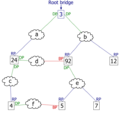
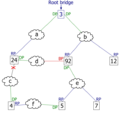
An example network. The numbered boxes represent bridges, that is switches in a LAN. The number is the bridge ID. The lettered clouds represent network segments. The smallest bridge ID is 3. Therefore, bridge 3 is the root bridge.
-
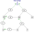
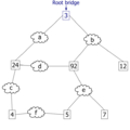
Path tie: The least-cost path to the root from network segment e goes through bridge 92. Therefore, the designated port for network segment e is the port that connects bridge 92 to network segment e.
See also
 In Spanish: Spanning tree para niños
