kids encyclopedia robot

Yagi–Uda antenna facts for kids

Kids Encyclopedia Facts
UHF TV Antenna 001
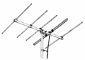
A modern high-gain UHF Yagi television antenna with 17 directors, and one reflector (made of four rods) shaped as a corner reflector
Yagi TV antenna 1954
Drawing of Yagi–Uda VHF television antenna from 1954, used for analog channels 2–4, 54–72 MHz (U.S. channels). It has five elements: three directors (to left) one reflector (to right) and a driven element which is a folded dipole (double rod) to match the 300 Ω twin lead feedline. The beam direction (direction of greatest sensitivity) is to the left.

A Yagi–Uda antenna, or simply Yagi antenna, is a directional antenna consisting of two or more parallel resonant antenna elements in an end-fire array; these elements are most often metal rods (or discs) acting as half-wave dipoles. Yagi–Uda antennas consist of a single driven element connected to a radio transmitter or receiver (or both) through a transmission line, and additional passive radiators with no electrical connection, usually including one so-called reflector and any number of directors. It was invented in 1926 by Shintaro Uda of Tohoku Imperial University, Japan, with a lesser role played by his boss Hidetsugu Yagi.

Reflector elements (usually only one is used) are slightly longer than the driven dipole and placed behind the driven element, opposite the direction of intended transmission. Directors, on the other hand, are a little shorter and placed in front of the driven element in the intended direction. These parasitic elements are typically off-tuned short-circuited dipole elements, that is, instead of a break at the feedpoint (like the driven element) a solid rod is used. They receive and reradiate the radio waves from the driven element but in a different phase determined by their exact lengths. Their effect is to modify the driven element's radiation pattern. The waves from the multiple elements superpose and interfere to enhance radiation in a single direction, increasing the antenna's gain in that direction.

Also called a beam antenna and parasitic array, the Yagi is widely used as a directional antenna on the HF, VHF and UHF bands. It has moderate to high gain of up to 20 dBi, depending on the number of elements used, and a front-to-back ratio of up to 20 dB. It radiates linearly polarized radio waves and is usually mounted for either horizontal or vertical polarization. It is relatively lightweight, inexpensive and simple to construct. The bandwidth of a Yagi antenna, the frequency range over which it maintains its gain and feedpoint impedance, is narrow, just a few percent of the center frequency, decreasing for models with higher gain, making it ideal for fixed-frequency applications. The largest and best-known use is as rooftop terrestrial television antennas, but it is also used for point-to-point fixed communication links, radar, and long-distance shortwave communication by broadcasting stations and radio amateurs.

Origins

FuG 220 and FuG 202 radar of Me 110 1945
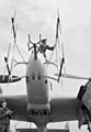
Quartet of two-dipole Yagi arrays (Hirschgeweih) of the German FuG 220 VHF-band radar on the nose of a late-World War II Bf 110 night fighter aircraft

The antenna was invented by Shintaro Uda of Tohoku Imperial University, Japan, in 1926, with a lesser role played by Hidetsugu Yagi.

However, the name Yagi has become more familiar, while the name of Uda, who applied the idea in practice or established the conception through experiment, is often omitted. This appears to have been due to the fact that Yagi based his work on Uda's pre-announcement and developed the principle of the absorption phenomenon Yagi had announced earlier. Yagi filed a patent application in Japan on the new idea, without Uda's name in it, and later transferred the patent to the Marconi Company in the UK. Incidentally, in the US, the patent was transferred to RCA Corporation.

Yagi antennas were first widely used during World War II in radar systems by Japan, Germany, the United Kingdom, and the United States. After the war, they saw extensive development as home television antennas.

Description

Yagi 3 element
Yagi–Uda antenna with a reflector (left), half-wave driven element (centre), and director (right). Exact spacings and element lengths vary somewhat according to specific designs.


The Yagi–Uda antenna typically consists of a number of parallel thin rod elements, each approximately a half wave in length. Rarely, the elements are discs rather than rods. Often they are supported on a perpendicular crossbar or "boom" along their centers. Usually there is a single dipole driven element consisting of two collinear rods each connected to one side of the transmission line, and a variable number of parasitic elements, reflectors on one side and optionally one or more directors on the other side. The parasitic elements are not electrically connected to the transmission line and serve as passive radiators, reradiating the radio waves to modify the radiation pattern. Typical spacings between elements vary from about 110 to 14 of a wavelength, depending on the specific design. The directors are slightly shorter than the driven element, while the reflector(s) are slightly longer. The radiation pattern is unidirectional, with the main lobe along the axis perpendicular to the elements in the plane of the elements, off the end with the directors.

Conveniently, the dipole parasitic elements have a node (point of zero RF voltage) at their centre, so they can be attached to a conductive metal support at that point without need of insulation, without disturbing their electrical operation. They are usually bolted or welded to the antenna's central support boom. The most common form of the driven element is one fed at its centre so its two halves must be insulated where the boom supports them.

The gain increases with the number of parasitic elements used. Only one reflector is normally used since the improvement of gain with additional reflectors is small, but more reflectors may be employed for other reasons such as wider bandwidth. Yagis have been built with 40 directors and more.

The bandwidth of an antenna is, by one definition, the width of the band of frequencies having a gain within 3 dB (one-half the power) of its maximum gain. The Yagi–Uda array in its basic form has a narrow bandwidth, 2–3 percent of the centre frequency. There is a tradeoff between gain and bandwidth, with the bandwidth narrowing as more elements are used. For applications that require wider bandwidths, such as terrestrial television, Yagi–Uda antennas commonly feature trigonal reflectors, and larger diameter conductors, in order to cover the relevant portions of the VHF and UHF bands. Wider bandwidth can also be achieved by the use of "traps", as described below.

Yagi–Uda antennas used for amateur radio are sometimes designed to operate on multiple bands. These elaborate designs create electrical breaks along each element (both sides) at which point a parallel LC (inductor and capacitor) circuit is inserted. This so-called trap has the effect of truncating the element at the higher frequency band, making it approximately a half wavelength in length. At the lower frequency, the entire element (including the remaining inductance due to the trap) is close to half-wave resonance, implementing a different Yagi–Uda antenna. Using a second set of traps, a "triband" antenna can be resonant at three different bands. Given the associated costs of erecting an antenna and rotator system above a tower, the combination of antennas for three amateur bands in one unit is a practical solution. The use of traps is not without disadvantages, however, as they reduce the bandwidth of the antenna on the individual bands and reduce the antenna's electrical efficiency and subject the antenna to additional mechanical considerations (wind loading, water and insect ingress).

Theory of operation

Two meter yagi
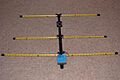
A portable Yagi–Uda antenna for use at 144 MHz (2 m), with segments of yellow tape-measure ribbon for the arms of the driven and parasitic elements.

Consider a Yagi–Uda consisting of a reflector, driven element and a single director as shown here. The driven element is typically a 12λ dipole or folded dipole and is the only member of the structure that is directly excited (electrically connected to the feedline). All the other elements are considered parasitic. That is, they reradiate power which they receive from the driven element. They also interact with each other, but this mutual coupling is neglected in the following simplified explanation, which applies to far-field conditions.

One way of thinking about the operation of such an antenna is to consider a parasitic element to be a normal dipole element of finite diameter fed at its centre, with a short circuit across its feed point. The principal part of the current in a loaded receiving antenna is distributed as in a center-driven antenna. It is proportional to the effective length of the antenna and is in phase with the incident electric field if the passive dipole is excited exactly at its resonance frequency. Now we imagine the current as the source of a power wave at the (short-circuited) port of the antenna. As is well known in transmission line theory, a short circuit reflects the incident voltage 180 degrees out of phase. So one could as well model the operation of the parasitic element as the superposition of a dipole element receiving power and sending it down a transmission line to a matched load, and a transmitter sending the same amount of power up the transmission line back toward the antenna element. If the transmitted voltage wave were 180 degrees out of phase with the received wave at that point, the superposition of the two voltage waves would give zero voltage, equivalent to shorting out the dipole at the feedpoint (making it a solid element, as it is). However, the current of the backward wave is in phase with the current of the incident wave. This current drives the reradiation of the (passive) dipole element. At some distance, the reradiated electric field is described by the far-field component of the radiation field of a dipole antenna. Its phase includes the propagation delay (relating to the current) and an additional 90 degrees lagging phase offset. Thus, the reradiated field may be thought as having a 90 degrees lagging phase with respect to the incident field.

Parasitic elements involved in Yagi–Uda antennas are not exactly resonant but are somewhat shorter (or longer) than 12λ so that the phase of the element's current is modified with respect to its excitation from the driven element. The so-called reflector element, being longer than 12λ, has an inductive reactance, which means the phase of its current lags the phase of the open-circuit voltage that would be induced by the received field. The phase delay is thus larger than 90 degrees and, if the reflector element is made sufficiently long, the phase delay may be imagined to approach 180 degrees, so that the incident wave and the wave reemitted by the reflector interfere destructively in the forward direction (i.e. looking from the driven element towards the passive element). The director element, on the other hand, being shorter than 12λ, has a capacitive reactance with the voltage phase lagging that of the current. The phase delay is thus smaller than 90 degrees and, if the director element is made sufficiently short, the phase delay may be imagined to approach zero and the incident wave and the wave reemitted by the reflector interfere constructively in the forward direction.

Interference also occurs in the backward direction. This interference is influenced by the distance between the driven and the passive element, because the propagation delays of the incident wave (from the driven element to the passive element) and of the reradiated wave (from the passive element back to the driven element) have to be taken into account. To illustrate the effect, we assume zero and 180 degrees phase delay for the reemission of director and reflector, respectively, and assume a distance of a quarter wavelength between the driven and the passive element. Under these conditions the wave reemitted by the director interferes destructively with the wave emitted by the driven element in the backward direction (away from the passive element), and the wave reemitted by the reflector interferes constructively.

In reality, the phase delay of passive dipole elements does not reach the extreme values of zero and 180 degrees. Thus, the elements are given the correct lengths and spacings so that the radio waves radiated by the driven element and those re-radiated by the parasitic elements all arrive at the front of the antenna in-phase, so they superpose and add, increasing signal strength in the forward direction. In other words, the crest of the forward wave from the reflector element reaches the driven element just as the crest of the wave is emitted from that element. These waves reach the first director element just as the crest of the wave is emitted from that element, and so on. The waves in the reverse direction interfere destructively, cancelling out, so the signal strength radiated in the reverse direction is small. Thus the antenna radiates a unidirectional beam of radio waves from the front (director end) of the antenna.

Design

There are no simple formulas for designing Yagi–Uda antennas due to the complex relationships between physical parameters such as

  • element length and spacing
  • element diameter
  • performance characteristics: gain and input impedance

However using the above kinds of iterative analysis, one can calculate the performance of a given a set of parameters and adjust them to optimize the gain (perhaps subject to some constraints). Since with an n element Yagi–Uda antenna, there are 2n − 1 parameters to adjust (the element lengths and relative spacings), this iterative analysis method is not straightforward. The mutual impedances plotted above only apply to λ/2 length elements, so these might need to be recomputed to get good accuracy.

The current distribution along a real antenna element is only approximately given by the usual assumption of a classical standing wave, requiring a solution of Hallen's integral equation taking into account the other conductors. Such a complete exact analysis, considering all of the interactions mentioned, is rather overwhelming, and approximations are inevitable on the path to finding a usable antenna. Consequently, these antennas are often empirical designs using an element of trial and error, often starting with an existing design modified according to one's hunch. The result might be checked by direct measurement or by computer simulation.

A well-known reference employed in the latter approach is a report published by the United States National Bureau of Standards (NBS) (now the National Institute of Standards and Technology (NIST)) that provides six basic designs derived from measurements conducted at 400 MHz and procedures for adapting these designs to other frequencies. These designs, and those derived from them, are sometimes referred to as "NBS yagis."

By adjusting the distance between the adjacent directors it is possible to reduce the back lobe of the radiation pattern.

History

The Yagi–Uda antenna was invented in 1926 by Shintaro Uda of Tohoku Imperial University, Sendai, Japan, with the guidance of Hidetsugu Yagi, also of Tohoku Imperial University. Yagi and Uda published their first report on the wave projector directional antenna. Yagi demonstrated a proof of concept, but the engineering problems proved to be more onerous than conventional systems.

Yagi published the first English-language reference on the antenna in a 1928 survey article on short wave research in Japan and it came to be associated with his name. However, Yagi who provided the conception which was originally vague expression to Uda, always acknowledged Uda's principal contribution towards the design which will currently be recognized as the reduction to practice, and if the novelty is not considered, the proper name for the antenna is, as above, the Yagi–Uda antenna (or array).

Nakajima J1N1-S Gekko land based night fighter at the Steven F. Udvar-Hazy Center
A Nakajima J1N1-S night fighter with quadruple Yagi radar transceiver antennas

The Yagi was first widely used during World War II for airborne radar sets, because of its simplicity and directionality. Despite its being invented in Japan, many Japanese radar engineers were unaware of the design until late in the war, partly due to rivalry between the Army and Navy. The Japanese military authorities first became aware of this technology after the Battle of Singapore when they captured the notes of a British radar technician that mentioned "yagi antenna". Japanese intelligence officers did not even recognise that Yagi was a Japanese name in this context. When questioned, the technician said it was an antenna named after a Japanese professor.

ASV Mk II radar transmitter antenna on Bristol Beaufort
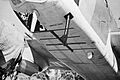
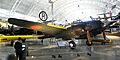
Close-up of Yagi arrays of the ASV Mark II radar fitted beneath a Bristol Beaufort aircraft for anti-submarine warfare

A horizontally polarized array can be seen on many different types of WWII aircraft, particularly those types engaged in maritime patrol, or night fighters, commonly installed on the lower surface of each wing. Two types that often carried such equipment are the Grumman TBF Avenger carrier-based US Navy aircraft and the Consolidated PBY Catalina long range patrol seaplane. Vertically polarized arrays can be seen on the cheeks of the P-61 and on the nose cones of many WWII aircraft, notably the Lichtenstein radar-equipped examples of the German Junkers Ju 88R-1 fighter-bomber, and the British Bristol Beaufighter night-fighter and Short Sunderland flying-boat. Indeed, the latter had so many antenna elements arranged on its back – in addition to its formidable turreted defensive armament in the nose and tail, and atop the hull – it was nicknamed the fliegendes Stachelschwein, or "Flying Porcupine" by German airmen. The experimental Morgenstern German AI VHF-band radar antenna of 1943–44 used a "double-Yagi" structure from its 90° angled pairs of Yagi antennas formed from six discrete dipole elements, making it possible to fit the array within a conical, rubber-covered plywood radome on an aircraft's nose, with the extreme tips of the Morgenstern's antenna elements protruding from the radome's surface, with an NJG 4 Ju 88G-6 of the wing's staff flight using it late in the war for its Lichtenstein SN-2 AI radar.

Montreal-tower-top.thumb2
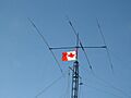
A three-element Yagi–Uda antenna used for long-distance (skywave) communication in the shortwave bands by an amateur radio station. The longer reflector element (left), the driven element (centre), and the shorter director (right) each have a so-called trap (parallel LC circuit) inserted along their conductors on each side, allowing the antenna to be used on more than one frequency band.

After World War 2, the advent of television broadcasting motivated extensive adaptation of the Yagi–Uda design for rooftop television reception in the VHF band (and later for UHF television) and also as an FM radio antenna in fringe areas. A major drawback was the Yagi's inherently narrow bandwidth, eventually solved by the adoption of the wideband log-periodic dipole array (LPDA). Yet the Yagi's higher gain compared to the LPDA makes it still required for the best fringe reception, and complicated Yagi designs and combination with other antenna technologies have been developed to permit its operation over the broad television bands.

The Yagi–Uda antenna was named an IEEE Milestone in 1995.

See also

  • Antenna (radio)
  • Antenna array
  • Numerical Electromagnetics Code
  • Radio direction finder
  • Radio direction finding
kids search engine
Yagi–Uda antenna Facts for Kids. Kiddle Encyclopedia.