
LC circuit facts for kids
An LC circuit is a special electronic circuit. It is made from two main parts: an inductor and a capacitor. These circuits are very useful for working with frequencies in electronic devices.
LC circuits can create signals at a specific frequency. They can also pick out a certain frequency from many different signals. Imagine tuning a radio; an LC circuit helps you find your favorite station! An ideal LC circuit has no resistance, meaning it doesn't waste energy as heat.
Contents
How LC Circuits Work
In an LC circuit, energy moves back and forth between the inductor and the capacitor. It's like a tiny electronic swing!
Energy in the Capacitor
A capacitor stores energy in its electric field. This energy depends on the electric charge stored on the capacitor.  Here, U is the energy, and q is the electric charge.
Energy in the Inductor
An inductor stores energy in its magnetic field. This energy depends on the electric current flowing through the inductor.  Here, U is the energy, and i is the electric current.
Energy Transfer
In an LC circuit, the total energy (U) is the sum of the energy in the capacitor and the energy in the inductor: 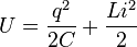 Because there is no resistance, this total energy stays the same. It just keeps moving between the capacitor and the inductor. This movement creates an oscillation or "vibration" of energy.
Resonant Frequency
Every LC circuit has a special frequency called its resonant frequency. At this frequency, the circuit works best. It's like the natural rhythm of the circuit.
The resonant frequency (f) is found using this formula: 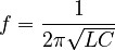 Here, L is the inductance of the inductor, and C is the capacitance of the capacitor.
Types of LC Circuits and Their Uses
LC circuits are often used as filters. This means they can either let certain frequencies pass through or block them.
Series LC Circuit
When an inductor and a capacitor are connected in a series, they form a series LC circuit. This type of circuit acts like a band-pass filter. This means it lets signals at or near its resonant frequency pass through easily. Signals at other frequencies are blocked.
For example, in a radio, a series LC circuit can help you pick out the specific radio station frequency you want to hear.
Parallel LC Circuit
When an inductor and a capacitor are connected in parallel, they form a parallel LC circuit. This circuit acts like a band-stop filter. This means it blocks signals at or near its resonant frequency. Signals at other frequencies can pass through.
A parallel LC circuit can be used to remove unwanted noise or interference at a specific frequency from a signal.
Images for kids
-
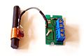
LC circuit (left) consisting of ferrite coil and capacitor used as a tuned circuit in the receiver for a radio clock
-
Animated diagram showing the operation of a tuned circuit (LC circuit). The capacitor C stores energy in its electric field E and the inductor L stores energy in its magnetic field B (green). The animation shows the circuit at progressive points in the oscillation. The oscillations are slowed down; in an actual tuned circuit the charge may oscillate back and forth thousands to billions of times per second.


See also
 In Spanish: Circuito LC para niños
