
Susitna River Bridge facts for kids
Quick facts for kids Susitna River Bridge |
|
|---|---|

Under construction, 1920
(view looking west, from upstream) |
|
| Carries | Alaska Railroad |
| Crosses | Sustina River |
| Locale | south-central Alaska |
| Characteristics | |
| Design | Through truss |
| Material | Steel |
| Height | 71 feet (22 m) |
| Longest span | 503 feet (153 m) |
| History | |
| Construction begin | October 1920 |
| Construction end | February 1921 |
|
Susitna River Bridge
|
|

Location in Alaska
|
|
| Location | Alaska Railroad Mile 264.1, North of Gold Creek, Matanuska-Susitna Borough, Alaska |
| Area | less than one acre |
| Built | 1921 |
| Architect | American Bridge Company |
| Architectural style | Through truss |
| NRHP reference No. | 77000227 |
| Significant dates | |
| Added to NRHP | September 15, 1977 |
The Susitna River Bridge, also known as the Gold Creek Bridge, is a very important bridge in Alaska. It was once the longest bridge span on the United States Government Railway. This bridge is made of strong steel and crosses the Susitna River.
The main part of the bridge is a 504-foot (154-meter) "through-truss" section. This means the train travels through the middle of the bridge's framework. The bridge was finished in February 1921. It also has other sections, including timber parts, making its total length about 1,322 feet (403 meters).
You can find the bridge about 150 miles (241 km) north of Anchorage. It is a historic landmark and was added to the National Register of Historic Places in 1977. This means it's recognized as a special place worth protecting.
Contents
Planning the Bridge
Engineers carefully studied the Susitna River before designing the bridge. They looked at how high the water and ice reached during floods. They saw that huge chunks of ice could jam up and cause the water to rise very high. This could easily destroy wooden bridge supports.
They realized that concrete supports would also be at risk from the ice and strong water currents. So, they decided to build one very long steel section. This long section would stretch across the main part of the river. It would only need two strong concrete supports on the riverbanks. This design was safer and worked better for the river's conditions.
The bridge also uses a mix of steel and timber (wood) sections. At the time, steel and concrete were very expensive. So, building some parts with timber was cheaper. The plan was to replace the timber parts with steel and concrete later on, when the timber wore out. This way, the bridge could be updated in the future.
Building the Foundations
Engineers dug deep test holes, up to 75 feet (23 meters) down. They found strong sand, gravel, and large rocks. This was a good base for the concrete supports, so they didn't need to use extra foundation piles.
.png)
Building the concrete supports (piers) started in May 1920. At first, supplies were brought by sleds over the ice. After the ice melted, they used boats and wagons. It became much easier when the railway tracks reached the river in September 1920.
Workers built a temporary wooden bridge (trestle) about 100 feet (30 meters) downstream. This allowed the railway tracks to continue past the bridge site. It also helped with building the main bridge without stopping train traffic.
For the north pier, they used an "open caisson" to dig. For the south pier, they used a "cofferdam." These are special structures that help keep water out of the digging area. Workers used large buckets to dig out the wet ground. Once they hit harder material, they pumped out the water and continued digging by hand.
Making the Concrete
Finding the right sand and gravel for the concrete was a big challenge. Local materials had too much "humus," which is decaying plant matter. This makes concrete weak. They finally found good sand and gravel from a glacier area, far away near Seward.
In September 1920, one of the piers partly failed. This was because of bad cement, the humus in the sand, and the very cold weather. So, they had to take special steps to pour the concrete.
The pit for the south pier was 33 by 69 feet (10 by 21 meters) and had 22 feet (6.7 meters) of water pressure from the river. It was too hard to keep the pit dry. Also, the water was very cold (35 degrees Fahrenheit or 2 degrees Celsius in November).
To solve this, they came up with a clever plan. They used a huge canvas sheet to cover the bottom of the pit. This sheet was shaped to let water flow around the edges. They also put steam coils around the pit and covered the whole area to keep it warm. The sand and gravel were heated with steam, and hot water was used to mix the concrete.
Concrete was poured for the south pier from October 24 to November 11, 1920. Temperatures during this time ranged from -2 to 48 degrees Fahrenheit (-19 to 9 degrees Celsius). For the north pier, concrete was poured from December 1 to December 18, 1920. Temperatures were even colder, from -12 to 34 degrees Fahrenheit (-24 to 1 degree Celsius). The concrete was given enough time to set and become strong before it touched the cold river water.
Putting the Steel Together
To build the 504-foot (154-meter) steel section quickly, they started before the piers were fully finished. They built the temporary wooden supports for this section from the north side. A temporary wooden bridge was also put in place to help with construction.
Building the steel part began on November 8, 1920, from the north end. They used a large 100-ton crane to lift the heavy steel pieces. By December 15, 1920, almost all the steel was in place. The last pieces were added by January 8, 1921.
The total weight of the steel in the main span was 1,803 tons. Workers started riveting (joining the steel pieces with special metal pins) after December 20, 1920. They worked even in very cold weather, sometimes as low as -42 degrees Fahrenheit (-41 degrees Celsius). The rivets put in during the cold were checked many times later and found to be very strong. About 42,200 rivets were used.
The main steel span was officially "swung" (meaning it was fully supported by its piers) on February 2, 1921. The first train crossed the bridge on February 6. The entire bridge, including the timber sections, was finished and ready for use by February 16, 1921.
Many people helped design and build this amazing bridge. Colonel F. Mears was in charge of the whole project. W. J. H. Fogelstrom and F. H. Chapin worked on the early designs. The American Bridge Company designed, built, and put together the steel parts. Other engineers also checked and approved the plans to make sure everything was safe and strong.
Images for kids
-
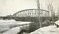
Under construction, 1920
(view looking west, from upstream) -
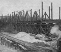
Erection of 504 foot span (November 29, 1920)
