
Breadboard facts for kids

A breadboard is a super handy tool for anyone who wants to build and test electronic circuits. It lets you connect different electronic parts without needing to solder them. This means you can easily try out new ideas and change your circuit if something doesn't work.
Think of a breadboard as a temporary building block for your electronics projects. It's perfect for making a prototype, which is like a first test version of something. Because you don't solder, you can reuse the breadboard again and again. This makes it very popular with students and people learning about electronics. You can use breadboards to build all sorts of circuits, from simple lights to more complex computer parts.
Contents
How Breadboards Changed Over Time

Long ago, when radio was new, people actually used wooden boards to build circuits. They would nail copper wires or metal strips to a piece of wood, sometimes even a real bread board! Then, they would solder electronic parts to these wires. It was a bit like drawing a map of the circuit on the board and then building on top of it. Sometimes, they used thumbtacks or small nails to hold things in place.
Over the years, breadboards changed a lot. The word "breadboard" now means any tool used to build test versions of electronic devices. For example, there were wooden boards with springs and even special printed circuit boards called "Printed Circuit Breadboards."
The most common type of breadboard today is usually made of white plastic. It's the "solderless" kind, which means you just plug parts into it. This modern design was created by Ronald J. Portugal in 1971.
Other Ways to Build Circuits
.jpg)
Besides breadboards, there are other ways to build test circuits. Some methods are similar to the old wooden breadboards, like point-to-point construction. Other methods include wire wrap and using boards like stripboards.
For very complex systems, like modern computers with millions of tiny parts, breadboards aren't usually used. It would be too hard to lay out and fix all those connections on a breadboard.
Today, many circuit designs are first made and tested using special computer programs. These programs can simulate how a circuit will work before anyone builds a physical version. This saves a lot of time and money. However, breadboards are still useful for some things, like testing radio frequency circuits, where computer models might not be perfect.
Understanding the Solderless Breadboard
What a Breadboard Looks Like
A modern solderless breadboard is a plastic block with many tiny holes. Underneath these holes are small metal clips, usually made of tin plated metal. These clips are called tie points or contact points. When you push a wire or a part's leg into a hole, the clip holds it tightly and makes an electrical connection.
The holes are usually spaced 0.1 inches (2.54 mm) apart. This is a standard size, so many electronic parts, like Integrated circuits (ICs) that look like black rectangles with legs, can fit perfectly. Wires and other parts like capacitors and resistors can also be plugged in. These clips can usually handle small amounts of electricity, like 1 ampere at 5 volts. Many breadboards have special edges that let you clip them together to make a bigger board.
How the Connections Work
Solderless breadboards come from different companies, but most of them have a similar design. They have two main types of areas, called "strips," which are groups of connected electrical points.

- Terminal strips
- These are the main areas where you plug in most of your electronic parts.
- In the middle of a terminal strip, you'll see a long groove or notch. This notch helps you place DIP ICs. On each side of this notch, there are rows of holes. Usually, five holes in a row are connected together electrically. This means if you plug a wire into one of these five holes, it's connected to anything else plugged into the other four in that same row. The rows on one side of the notch are often labeled A, B, C, D, E, and on the other side F, G, H, I, J. When you plug in an IC, its pins go into rows E and F, straddling the notch. The columns of holes are usually numbered, like 1 to 50.
- Bus strips
- These strips are mainly used to provide power to your electronic parts.
- A bus strip usually has two rows: one for the positive power supply (often marked in red) and one for the negative or ground connection (often marked in blue or black). Some breadboards only have one power row on each side. Sometimes, all the holes in a power column are connected. Other times, they are connected in smaller groups (like 25 holes at a time). This gives you more control over the power supply.
- Bus strips are usually found along the long sides of the terminal strips. On larger breadboards, you might find extra bus strips at the top and bottom.
- It's good to know that the way power bus strips are lined up can be different between small and large breadboards. This means some accessories, like those for a Raspberry Pi, might only fit certain types of breadboards. There isn't one official standard, so always check pictures or descriptions to make sure parts will work together!
Some companies sell separate bus and terminal strips, while others combine them into one block. You can often clip strips or blocks from the same brand together to create a bigger breadboard for larger projects.
For a more stable setup, some breadboards are mounted on a metal sheet. This sheet often has special connectors called binding posts. These posts make it easy to connect an outside power supply to your breadboard. This type of breadboard can be a bit easier to work with. You can see examples of these in the images below.
Images for kids
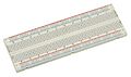
-
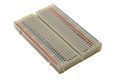
A 400-point solderless breadboard.
-
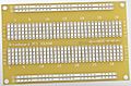
A 400-point printed circuit board (PCB) breadboard, another type of prototyping board.
-
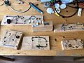
Educational circuits built on blocks of wood.
-
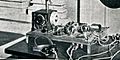
An example of how "breadboards" were used in early electronics, from a 1922 magazine.
-
A solderless breadboard with power strips on both sides.
-
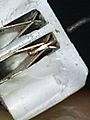
A look inside a solderless breadboard strip, showing the metal clips.
-
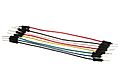
Colorful wires used to connect parts on a breadboard.
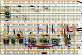
-
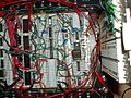
A complex circuit built using a microprocessor on a breadboard.
-
A prototype microphone amplifier built with tiny parts on adapter boards.


.jpg)


See also
 In Spanish: Placa de pruebas para niños
