Dipole antenna facts for kids
A dipole antenna is a very common and important type of radio antenna. It is often used by itself to send or receive radio signals. It also forms a key part of many other antenna designs, acting as the main part that sends out or picks up radio waves.
Contents
What is a Dipole Antenna?
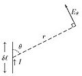
A dipole antenna is made of two straight pieces of metal, like wires or rods. When a radio signal (which is an electric current) flows into these pieces, it creates electromagnetic waves, also known as radio waves. These waves then travel through the air.
To work best, a dipole antenna is usually cut to a special length. This length is chosen so the antenna "resonates" with the radio signal. For most dipole antennas, this special length is about half the wavelength of the radio signal it's designed for.
How Long Should a Dipole Antenna Be?

The length of a dipole antenna is super important because it decides which frequency (or channel) the antenna will work best on. The antenna needs to be an "electrical half wavelength" or a multiple of that.
This "electrical" length is a bit different from the actual wavelength of a radio signal traveling through the air. This is because the metal of the antenna affects the speed of the signal slightly. So, an antenna will be a little bit shorter than what you might calculate for a wave in open air.
To find the right length for a half-wave dipole, you first calculate the half-wavelength for the signal in air. Then, you multiply this number by a special factor, usually between 0.96 and 0.98. This factor depends on things like how thick the wire or tube used for the antenna is compared to its length.
Common Uses of Dipole Antennas
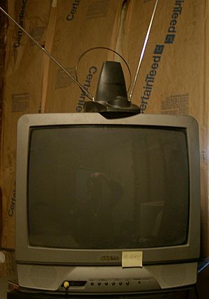
Dipole antennas are used in many everyday devices. You might have seen them as "rabbit ears" on older television sets. They are also popular for shortwave radio antennas, which people use to listen to radio stations from far away. Many whip antennas, like those on cars, are also types of dipole antennas.
Images for kids
-
A diagram of a half-wave dipole antenna that a shortwave listener might build.
-
Animated diagram of a half-wave dipole antenna receiving a radio wave. The antenna consists of two metal rods connected to a receiver R. The electric field (E, green arrows) of the incoming wave pushes the electrons in the rods back and forth, charging the ends alternately positive (+) and negative (−). Since the length of the antenna is one half the wavelength of the wave, the oscillating field induces standing waves of voltage (V, represented by red band) and current in the rods. The oscillating currents (black arrows) flow down the transmission line and through the receiver (represented by the resistance R).
-
Animation of a transmitting half wave dipole showing the voltage V(x) (red, ) and current I(x) (blue, ) due to the standing wave on the antenna. Since the standing wave is mainly storing energy, not transporting power, the current is not in phase with the voltage but 90° out of phase. The transmission line applies an oscillating voltage V_\text{i}\cos \omega t from the transmitter between the two antenna elements, driving the sinusoidal oscillation. The feed voltage step has been increased for visibility; typical dipoles have a high enough Q factor that the feed voltage is much smaller in relation to the standing wave. Since the antenna is fed at its resonant frequency, the input voltage is in phase with the current (blue bar), so the antenna presents a pure resistance to the feedline. The energy from the driving current provides the energy radiated as radio waves. In a receiving antenna the phase of the voltage at the transmission line would be reversed, since the receiver absorbs energy from the antenna.
-
Length reduction factor for a half-wave dipole to achieve electrical resonance (purely resistive feedpoint impedance). Calculated using the induced EMF method, an approximation that breaks down at larger conductor diameters (dashed portion of graph).
-
"Rabbit-ears" VHF television antenna (the small loop is a separate UHF antenna).
See also
 In Spanish: Dipolo (antena) para niños
 | Calvin Brent |
 | Walter T. Bailey |
 | Martha Cassell Thompson |
 | Alberta Jeannette Cassell |


