
GL Mk. I radar facts for kids
| Country of origin | UK |
|---|---|
| Introduced | Mk. I late 1939 Mk. I* early 1941 |
| Type | AA direction |
| Frequency | 54.5 to 85.7 MHz |
| PRF | 1.5 kHz |
| Pulsewidth | 3 µs |
| Azimuth | ±20° from current bearing |
| Precision | 50 m in range |
| Power | 50 kW |
| Other Names | Radar, Anti-Aircraft No. 1, Mk. 1 |

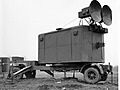
GL Mk. II transmitter van
|
|
| Country of origin | UK |
|---|---|
| Introduced | late 1941 |
| Type | AA direction |
| Frequency | 54.5 to 85.7 MHz |
| PRF | 1 to 2.5 kHz |
| Pulsewidth | 1 to 1.2 µs |
| Range | 50,000 yd (46 km) yards detection 30,000 yd (27 km) tracking 14,000 yd (13,000 m) gun direction |
| Azimuth | ±20° from current bearing |
| Elevation | 15–45° |
| Precision | 50 m (55 yd) in range, under 0.5° directionally |
| Power | 150 kW |
| Other Names | Radar, Anti-Aircraft No. 1, Mk. 2, SON-2 |
The Radar, Gun Laying, Mark I, or GL Mk. I, was an early radar system. It was created by the British Army to help anti-aircraft artillery (AA guns) find how far away enemy planes were. This radar helped gunners aim better during World War II.
There were two main upgrades to the GL Mk. I. The first was the GL/EF (Elevation Finder). It added the ability to find the target's direction and height more accurately. The second was the GL Mk. II, which was even more precise.
The first GL radar was a simple design from 1935. It used separate parts for sending and receiving radio signals. These parts were in wooden cabins on wheels. Each cabin had its own antennas that had to be turned to point at the target. The early GL Mk. I could only tell how far away a target was. It was not very good at showing the exact direction or height.
About 410 Mk. I and slightly improved Mk. I* units were made. Later, the Mk. II was developed. It was much more accurate and could guide the guns directly. The Mk. II helped reduce the number of shots needed to hit an aircraft. About 1,679 Mk. II units were produced. Some were even sent to the Soviet Union and called SON-2.
Newer radars, like the GL Mk. III radar and later the SCR-584, eventually replaced the GL Mk. II. However, the Mk. II stayed in use for other tasks.
How Radar Was Developed
The Army's Radar Team
The idea of radar in the UK first came up in 1930. Two Army scientists, W. A. S. Butement and P. E. Pollard, suggested building a radar to find ships. They even made a small test model. However, the Army was not interested at the time.
In 1936, the Air Ministry successfully showed off its radar system, which became Chain Home. This made the Army suddenly very interested. They visited the radar team and saw smaller, mobile radar units. These seemed useful for the Army. So, on October 16, 1936, the Army formed its own radar group, called the Army Cell. Butement and Pollard were part of this team.
The Army Cell's first job was to improve anti-aircraft fire. The biggest challenge was accurately measuring how far away planes were. Optical tools could find direction and height, but rangefinding was hard and slow. A radar that could quickly and accurately find range would greatly help. Their goal was to measure range within 50 yards (46 m) at a distance of 14,000 yards (13 km).
Building the Mk. I Radar
The GL radar project started early, using long radio waves. These waves were easy to create with existing radio equipment. However, long waves needed very large antennas, which were not practical for mobile systems. As new electronics were developed, radar systems could use shorter waves. This made antennas smaller and easier to move.
Early radar displays, like those used for Chain Home, showed a line on a screen. When a radio signal bounced back from an object, it made a small "blip" on this line. The distance to the object was measured by looking at where the blip appeared on a scale. But this method wasn't accurate enough for aiming guns.
To get better accuracy, Pollard designed a new system. It used the entire screen to show only a small range of distances. This allowed for very precise measurements. By late 1937, the test system could measure aircraft range within 25 yards (23 m).
The GL Mk. I system used two receiver antennas. They were placed so that when they pointed directly at a target, the signals would cancel out. This created a "null" on a second display. An operator would try to keep the antennas pointed at the target by keeping this null.
The transmitter was in a large wooden cabin on a trailer. It had one antenna that sent out a wide signal, about 60 degrees on each side. The receiver cabin was smaller and could rotate. It had three antennas for range and direction.
First Uses of the Radar
By 1939, the GL Mk. I was ready for production. Companies like Metropolitan-Vickers and A.C. Cossor built the units. By the end of 1939, 59 systems were ready, and 344 more were made in 1940.
The system was good at measuring range (about 50 yards (46 m) accuracy). However, it had problems in real battles. By late 1939, night bombing was a big worry. The GL Mk. I could not give accurate direction or height information. This meant it couldn't guide guns at night. Instead, old methods were used, like searchlights trying to find planes. This was not very effective.
During The Blitz (heavy German bombing of Britain), the Army's air defense struggled. General Frederick Pile, who led the Anti-Aircraft Command, said it was "bitterly disappointing." The radar had many "teething troubles."
The GL Mk. I was not good at finding targets. Moving the whole system to track a target was hard. Also, the displays only showed a small part of the sky. The direction accuracy was only 20 degrees. This was enough to keep the antennas aimed, but not enough to direct optical instruments. If more than one plane entered the radar's wide signal, the system got confused. Operators couldn't tell which plane they were tracking.
Radar at Dunkirk
GL Mk. I radars were used by the British Expeditionary Force in France. During the Dunkirk evacuation, these radars had to be left behind.
German radar experts, led by Wolfgang Martini, put together the captured radars. They were not impressed. German radars like Freya and Würzburg were more advanced. They used much shorter radio waves. This led the Germans to think British radar was not very good. They underestimated its importance before the Battle of Britain.
Improving the Radar: Mk. II
The GL team had already started planning a much better radar. This new version would provide accurate direction and height information. They wanted the GL system to guide the guns completely.
To do this, they used a new method called "lobe switching." This involved using two antennas aimed slightly differently. When a target was exactly in the middle, both antennas would receive an equal signal. By switching between the two signals, the operator could tell if the target was off-center. They would then rotate the antennas until the signals were equal. This allowed for very accurate direction measurements, sometimes as precise as half a degree.
The Mk. I* and Bedford Attachment
As the Mk. I was being used, some electronic improvements were made. These were put into a new version called the Mk. I*. It had better signal quality and anti-jamming features.
By late 1939, it was clear the Mk. I wasn't enough, especially at night. The Mk. II wouldn't be ready until 1941. So, Leslie Bedford suggested an easier fix. He proposed adding parts of the Mk. II's antenna and display systems to the Mk. I.
This led to the GL/EF, also known as the Bedford Attachment. It added vertical antennas and a new screen to measure height. It also had a special device called a radiogoniometer to measure the vertical angle accurately. Mk. I* units with the GL/EF started being used in early 1941, during the peak of The Blitz.
With the Bedford Attachment, the Army finally had a complete gun-laying system. The radar could continuously provide all the information needed. This meant the guns could be aimed automatically or with simple pointers. Even the fuse settings for the shells were set automatically. The whole process became much more automated.
Solving Calibration Problems

At this point, a big problem with calibration appeared. Early radars used long radio waves that bounced off the ground. These reflected signals interfered with the main signal. This made it hard to find targets, especially their height.
The problem was that these "nulls" (areas where the signal was weak) moved around as the antennas turned. It was hard to fix this with simple adjustments. Leslie Bedford suggested a solution: instead of calibrating the radar, they should calibrate the ground. This meant flattening the area around the radar station with a metal wire mat.
Nevill Mott, a physicist, designed these mats. They were large octagons, about 130-yard (120 m) wide, made of wire mesh. They were held up in the air by hundreds of wires and wooden stakes. The radar system itself had to be raised on blocks to be above the mat.
Building these mats was a huge effort. Each mat used a lot of wire and took about 50 men four weeks to build. By early 1941, only 10 sites had these mats. The program continued for years until newer radars that didn't need mats were introduced.
Another issue was that barrage balloons could block the radar signal. This was a problem because balloons were often used near AA guns to protect important targets.
Amazing Results
In September 1940, General Pile brought in Patrick Blackett, a scientist, to help improve air defense. Blackett used a mathematical approach to study the problem. This led to the field of operational research.
Blackett formed a study group called "Blackett's Circus." They studied how to use radar data to predict enemy positions. They also helped design simpler plotting machines.
In November 1940, a gunnery school was set up. They found that it was easy to make mistakes when putting information into the gun predictors (analog computers that calculated where to aim). Leslie Bedford again helped by creating "Trainers" for operators to practice.
A special trailer was added to some AA sites to record data. This helped them find ways to improve. Between September and October 1940, 260,000 AA rounds were fired, destroying 14 aircraft. This was a rate of 18,500 shots per kill. Before radar, it was 41,000 shots per kill. With the GL/EF, ground mats, and better training, this improved to 4,100 shots per kill by 1941.
General Pile noted the great improvement. He said that on May 11–12, 1941, they destroyed 9 enemy planes and damaged many more. He stated that The Blitz "virtually ended that night." By the end of The Blitz, 170 night raiders were destroyed.
The Mk. II Arrives
Production of the GL Mk. II began in early 1941. It was built by the Gramophone Company and Cossor. The Mk. II had separate screens for range, direction, and height. This allowed continuous tracking of targets.
The Mk. II also had a new, more powerful transmitter (150 kW). This gave it better range and allowed for shorter radio pulses. Shorter pulses meant more accurate measurements. The Mk. II could measure direction within half a degree. This was accurate enough to aim the guns directly.
The Mk. II mostly replaced the Mk. I* by mid-1942. It stayed in service until 1943. Analysis showed that the Mk. II further improved the accuracy, reducing the shots per kill to 2,750. In total, 1,679 GL Mark II sets were made between June 1940 and August 1943.
Developing the Mk. III Radar

In 1940, the invention of the cavity magnetron changed radar. It allowed radars to use much shorter microwave wavelengths. This meant antennas could be very small, just a few centimeters long. These small antennas could be placed in front of parabolic reflectors, which focused the signal into a very narrow beam.
These new microwave radars, like the GL Mk. III radar, were much more mobile. They came on two-wheeled trailers. Because their beams were so narrow, they didn't have problems with ground reflections. This meant they didn't need the large wire ground mats. They could be set up and ready to use in just a few hours.
The new microwave sets started replacing the Mk. II in 1943. However, they were not produced very quickly. In 1944, the US SCR-584 radar arrived. This radar was even better, combining scanning and tracking into one unit. After the war, these were replaced by the smaller AA No. 3 Mk. 7 radar. AA guns were removed from service in the late 1950s.
How the Radars Worked
Basic Mk. I Design
The GL Mk. I used two antennas: one for sending signals and one for receiving them. Both were on top of wooden huts, like small trailers. These huts held the electronic equipment. The huts could rotate to track targets. A generator between them provided power.
The Mk. I transmitter sent out 3 microsecond (µs) long pulses. It had up to 50 kW of power, sending 1,500 pulses per second. These signals spread out in a wide fan shape. A lot of the signal hit the ground. Because of the long radio waves, this signal bounced forward. This caused interference with the main signal. The GL mat was used to make these reflections more predictable.
The receiver units could work on different frequency bands. They used a common oscillator and vacuum tubes. The frequency could be switched between two bands: 54.5 to 66.7 MHz and 66.7 to 84.0 MHz.
GL/EF (Bedford Attachment)
The GL/EF system was similar to the Mk. I but added more antennas. These new antennas were placed vertically on a ladder-like structure on top of the receiver cabin. The original range antenna was at the bottom. Two new antennas were spaced out along the ladder.
An electronic switch rapidly changed the input to the receivers. It switched between the range antenna and the new elevation antennas. This created two traces on a new screen for elevation measurements. The top trace showed the range, and the bottom trace showed the elevation. The operator would turn a dial until the signal on the bottom trace disappeared (a "null"). This showed the correct elevation angle.
Later improvements allowed for continuous tracking. If the signal was not perfectly aligned, a faint second blip would appear. This helped the operator adjust the antennas.
Mk. II Improvements

The Mk. II system was much like the Mk. I* with GL/EF. However, it had many small improvements that made it more accurate. These included a more powerful transmitter and updated receivers. The shorter pulse width also allowed for more precise measurements.
A key difference was how the Mk. II created the "split-traces" on its displays. It used a mechanical system with two antennas aimed slightly differently. Their reception patterns overlapped in the middle. By comparing the signal strength from each, the operator could tell if the target was centered. They would rotate the antennas until both signals were equal.
The Mk. II used one receiver for each pair of antennas. A switch quickly alternated the signals into the receiver. One signal was slightly delayed. This created two slightly separated blips on the screen. The operator would compare the length of the blips. They would then rotate the antenna until the blips were equal, meaning the target was centered.
The Mk. II also solved the problem of multiple aircraft appearing on the screen. It added a second transmission antenna system. One antenna had a wide beam for searching. The other had a much narrower beam for tracking a single target. The operator would use the wide beam to find a target, then switch to the narrow beam for tracking.
The Mk. II also included a simple way to calibrate. A telescope was attached to the elevation control. For calibration, the elevation would be set to zero, and the telescope would point at the horizon. Then, a balloon would be launched and tracked by the radar. This helped make sure the radar was accurate.
Images for kids
-

GL Mk. II transmitter van
-
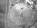
Aerial photo of a gun laying mat installed on the east coast, north of Sunderland. The ramp and platform at the centre are prominent.
-
GL Mk. III C radar
-
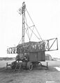
Transmitter cabin of the Mk. II radar. The individual antennas can just be made out. This version appears to combine the wide and narrow angle antennas on a single unit.
