Chain Home facts for kids
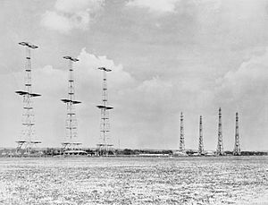
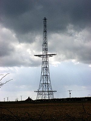
Chain Home at RAF Poling, West Sussex
|
|
| Country of origin | UK |
|---|---|
| Manufacturer | Metropolitan-Vickers, AC Cossor |
| Designer | AMES |
| Introduced | 1938 |
| Type | early warning |
| Frequency | between 20 and 55 MHz |
| PRF | 25 pps |
| Beamwidth | 150º |
| Pulsewidth | 6 to 25 µs |
| Range | 160 km (99 mi) |
| Azimuth | 150º |
| Elevation | 2.5 to 40º |
| Precision | 8 km (5.0 mi) or better (1 kilometre (0.62 mi) typical) in range, ±12º in azimuth (typically less) |
| Power | 100 kW to 1 MW depending on version |
| Other Names | RDF, RDF1, AMES Type 1, AMES Type 9 |
Chain Home, or CH for short, was a secret network of radar stations. The Royal Air Force (RAF) built them along the coast of Britain before and during World War II. Their job was to spot enemy aircraft coming towards the UK.
At first, this system was called RDF. Later, its official name became Air Ministry Experimental Station Type 1 (AMES Type 1). Chain Home was the very first radar network in the world used for military purposes. It helped Britain a lot during the war, especially in the Battle of Britain. Many people called it one of the most powerful weapons in the "Wizard War" because of its amazing effect.
Contents
How Chain Home Worked
In 1934, a group of experts asked a radio scientist named Robert Watson-Watt to look into claims about "radio death rays." His assistant, Arnold Wilkins, showed that death rays were not possible. However, he suggested that radio waves could be used to find objects far away.
The Daventry Experiment
In February 1935, they set up a test. They used a receiver near a BBC radio transmitter. An airplane flew around the area. A screen connected to the receiver showed a pattern when the plane's radio waves bounced back. This proved the idea worked!
Money was quickly given for more research. Watt's team built a test transmitter that sent out short bursts of radio waves, called pulses. On June 17, 1935, they successfully measured how far away an airplane was. By the end of that year, they could detect planes up to 160 kilometers (100 miles) away.
Building the Network
The first five Chain Home stations were set up by 1937. They protected the area around London and started working full-time in 1938. Early tests showed it was hard to get the radar information to fighter aircraft pilots quickly. This led to the creation of the Dowding system. This system gathered all the radar information and sent it to a central control room. There, experts filtered the data and gave clear instructions to the pilots.
By the time the war started in 1939, dozens of CH stations were ready. They covered most of the eastern and southern coasts of the UK. A huge network of private telephone lines connected them all.
Chain Home in Battle
Chain Home was incredibly important during the Battle of Britain in 1940. CH systems could spot enemy planes gathering over France. This gave RAF commanders plenty of time to get their fighters ready. This early warning made the RAF much more effective. It was like having three times as many fighters! This helped them defeat the often larger German air forces.
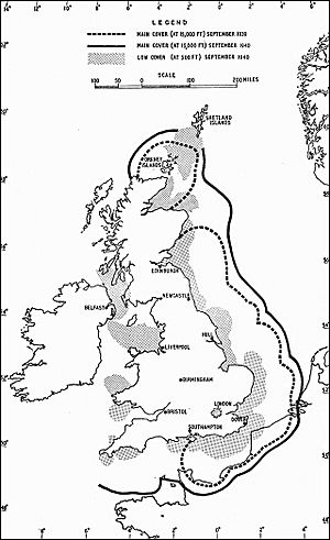
The Chain Home network kept growing. By the end of the war, there were over 40 stations. CH systems were not good at finding planes flying very low. So, from 1939, they were often paired with the Chain Home Low system (AMES Type 2). This system could detect planes flying as low as 150 meters (500 feet). Ports were protected by Chain Home Extra Low, which could see planes down to 15 meters (50 feet) but only at shorter distances.
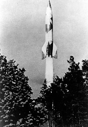
Later in the war, around 1942, newer AMES Type 7 radars started tracking targets. Chain Home then focused mainly on giving early warnings. Towards the end of the war, when German bombing stopped, CH systems were used to detect V2 missile launches.
After the war, the UK's radar systems were reduced. But when the Cold War began, Chain Home radars were used again in a new system called ROTOR. They stayed in use until newer systems replaced them in the 1950s. Today, only a few of the original sites remain.
How Radar Was Invented in the UK
Early Radio Ideas
From the very beginning of radio technology, people used radio signals to find directions. This was called radio direction finding (RDF). It could tell you the direction of a radio transmitter. People also knew that metal objects reflected radio signals. This led to ideas about finding objects by sending out a signal and listening for reflections.
In the early 1930s, people started thinking about using radio to find aircraft. But these early systems could only tell you the direction, not how far away something was. This made them hard to use for fast-moving planes.
Watt's Breakthrough
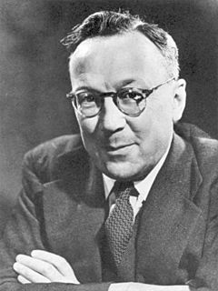
Robert Watson-Watt worked for the Met Office, studying radio signals from thunderstorms. In 1922, he found a way to quickly find the direction of a signal using a cathode ray tube (CRT). This system was later called huff-duff.
Around the same time, Edward Appleton was doing experiments. He used radio signals to measure the distance to layers in the atmosphere, like the ionosphere. Watt learned from these experiments.
In 1931, Arnold Frederic Wilkins joined Watt's team. He found a report from the General Post Office (GPO) that said airplanes flying near a radio receiver caused the signal to change. Wilkins realized that a bomber's wingspan was just the right size to reflect shortwave radio signals very well.
The "Death Ray" Question
For years, inventors claimed to have built "death rays" that could destroy things with radio energy. There were also stories about Germany building radio weapons that could stop car engines. The Air Ministry was skeptical but couldn't ignore these claims. If such weapons existed, they could make bombers useless.
In 1934, a committee was formed to study new air defense ideas. Harry Wimperis asked Watt about the "death ray" concept. Watt asked Wilkins to calculate how much energy would be needed. Wilkins quickly showed that a death ray was impossible with the technology of the time.
But Wilkins then remembered the GPO report about planes affecting radio signals. He suggested that if a death ray wasn't possible, maybe radio waves could be used to detect planes instead. Watt wrote to the committee saying the death ray was unlikely, but "radio detection" was "less unpromising."
The Daventry Test
The committee was very interested. They gave £4,000 to start development. But Hugh Dowding, a top RAF officer, wanted a real demonstration.
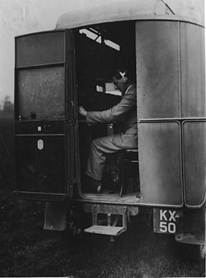
Wilkins suggested using a powerful BBC shortwave radio station in Daventry. On February 26, 1935, they put a receiver and a screen in a van. They parked it in a field and set up antennas. A Handley Page Heyford plane flew over. The screen clearly showed effects from the plane's reflection!
Watt was so excited he reportedly said, "Britain has become an island again!" Dowding was also very impressed. Days later, more money was given for development. A small team began working on the secret project.
Building the First System
Edward George Bowen joined the team to build a transmitter. He created a system that sent out 25-kilowatt signals at 6 MHz, sending 25-microsecond pulses 25 times a second. Meanwhile, Wilkins built the receiver.
The team moved their equipment to Orfordness in May 1935. They set up antennas on old huts. At first, it didn't work well against planes, but they saw reflections from the ionosphere far away. Bowen kept increasing the power of the transmitter.
On June 17, 1935, the system was turned on. It immediately showed reflections from an object 27 kilometers (17 miles) away! They tracked it until it disappeared. Watt called the nearby seaplane station and found out a Supermarine Scapa flying boat had just landed. This moment is considered the official birth of radar in the UK.
Planes from RAF Martlesham Heath then helped with tests. The detection range kept increasing. By the end of 1935, it was 130 kilometers (80 miles), and by early 1936, over 160 kilometers (100 miles).
Planning the Chain
In August 1935, the term "Radio Direction and Finding" (RDF) was created. Watt suggested building a network of stations along the entire east coast, about 32 kilometers (20 miles) apart.
The Orfordness system was very effective, even though it was built quickly. It was much better than older acoustic mirror systems, which could only detect planes up to 8 kilometers (5 miles) away. Work on those older systems stopped. In December 1935, a contract was given to build five RDF stations along the south-east coast.
Not everyone was convinced. Frederick Lindemann, a scientist and friend of Winston Churchill, preferred infrared systems. But his ideas were not practical. Eventually, the committee was reorganized without him.
As the project grew, Watt asked for a central research station. The team found Bawdsey Manor in Suffolk. It was high above sea level and had a large house for labs. In 1936, the team moved to Bawdsey Manor and created the Air Ministry Experimental Station (AMES).
Ready for Production
The system was designed using existing commercial technology to make it ready faster. They first used a 50-meter wavelength (around 6 MHz). But as new radio broadcasts caused interference, they switched to shorter wavelengths, eventually settling on 10 to 13 meters (20-30 MHz). This also allowed them to change frequencies to avoid jamming.
In 1937, they added a way to measure the height of planes. This used several antennas at different heights on the receiver masts. With this, the system was complete and ready for production.
Companies like Metropolitan-Vickers built the transmitters, and AC Cossor built the receivers. In August 1937, the government approved full deployment. The first five stations became operational in September 1938, during the Munich crisis.
The Dowding System
Tests in 1936 and 1937 showed that while radar could detect planes, getting the information to fighter pilots was hard. Pilots were getting too many confusing reports. This led to the creation of the Dowding system.
This system used a huge network of telephone lines. Reports from radar stations went to a central "filter room" in London. There, experts combined and filtered the information into a single, clear picture of the sky. This information was then sent to the pilots. This system needed many people to operate it.
By September 1939, 21 Chain Home stations were working. After the Battle of France in 1940, the network grew to cover the west coast and Northern Ireland. By 1940, it stretched from Orkney in the north to Weymouth in the south. This meant almost all of Britain's coast facing Europe was covered.
The rapid growth of CH meant they needed many technical staff. In 1940, Canada sent over 1,200 trained personnel to help as radar mechanics.
Battle of Britain Success
During the Battle of Britain, German planes attacked Chain Home stations several times. For example, the station at Ventnor, Isle of Wight, was attacked. Although the wooden huts were damaged, the strong steel towers survived. Because the towers were still standing, the Luftwaffe thought the stations were too hard to destroy. They mostly left them alone for the rest of the war.
This meant CH could operate without much interference during the Battle of Britain. The Dowding system, with its excellent communication, made British fighters much more effective. Some German raids were met by every British fighter sent out, while German planes often returned home without seeing any enemy aircraft. This is why Winston Churchill said Chain Home helped win the Battle of Britain.
Later Uses and Upgrades
By 1942, the more advanced AMES Type 7 radar systems took over many of CH's duties. Type 7 radars could scan a full 360 degrees and show a real-time map of the airspace. This made it easier to guide fighters. CH then became mainly an early warning system.
To make operations simpler, a special machine called "The Fruit Machine" was added. This was an analogue computer that took information directly from the radar operator. It calculated the exact location of targets, which could then be plotted on a map or sent by phone.
The original transmitters were also upgraded. Their power increased from 100 kilowatts to 750 kilowatts, which greatly increased their range.
Detecting V-2 Rockets
In September 1944, Germany started attacking Britain with V-2 rockets. These rockets flew too high and too fast to be detected during their approach. This meant there was no time for air raid warnings.
Several CH stations were reorganized into the "Big Ben" system to detect V-2 launches. They were set to their maximum range and altitude-measuring mode. As a missile climbed, it would pass through different sensitive areas of the radar, causing blips to appear and disappear. Operators measured the range to the rocket as it flew. This information was sent to a central station.
At the central station, these measurements were plotted as arcs on a chart. Where the arcs crossed, it showed the approximate launch area. This helped determine the rocket's path and allowed air raid warnings to be sent to likely target areas. The V-2's metal body was very good at reflecting the radar signals.
Post-War Use and Today
After the war, many British radar sites were closed. But with the start of the Cold War, some wartime radars were brought back into service. Chain Home radars were used in the new ROTOR system until they were replaced by newer systems in the 1950s.
Today, some of the tall steel transmitter towers still stand. The wooden receiver towers have all been taken down. The remaining steel towers are now used for other purposes. Some are protected as historic buildings. For example, a 110-meter (360-foot) transmitter tower is at the BAE Systems facility in Great Baddow, Essex. It was moved there in 1956.
The Swingate transmitting station in Kent still has two original towers, used for microwave relays. RAF Stenigot in Lincolnshire has another almost complete tower, used for training.
The only original Chain Home site still used as a military radar station is RRH Staxton Wold in North Yorkshire. However, none of the original 1937 equipment remains there.
How Chain Home Looked and Worked
Station Layout
A Chain Home radar station usually had two main parts. One area had the tall transmitter towers and their buildings. A second area, usually a few hundred meters away, had the receiver masts and the building where the operators worked. The CH system was a "bistatic radar," meaning its transmitter and receiver were in different places.
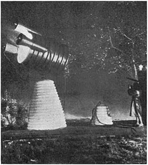
The transmitter had four steel towers, each 110 meters (360 feet) tall. They were set in a line about 55 meters (180 feet) apart. Antennas were strung between these towers. These antennas sent out a strong, fan-shaped radio signal, covering about 100 degrees. This signal was aimed out over the water.
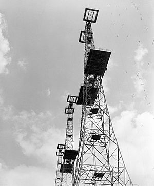
The receiver had four wooden towers, each 73 meters (240 feet) tall. They were arranged in a square. Each tower had three sets of receiver antennas at different heights. Operators could choose which antenna to use.
Transmitter Details
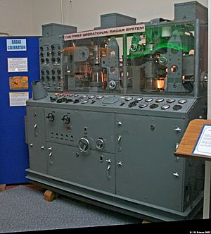
The Type T.3026 transmitter sent a pulse of radio energy into the antennas. Each station had two of these transmitters. The signal filled the space in front of the antenna. The signal was strongest directly in front and weaker to the sides.
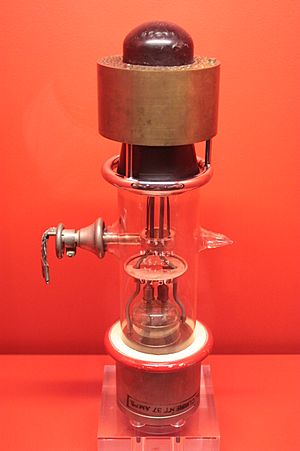
The transmitters used special "demountable" valves that could be opened for service. They had to be connected to a vacuum pump while working. The valves could operate on one of four frequencies between 20 and 55 MHz. They could switch frequencies in just 15 seconds.
To avoid interference between stations, the timing of their broadcasts was carefully controlled. Each station was set to trigger its signal at a slightly different moment.
Receiver Details
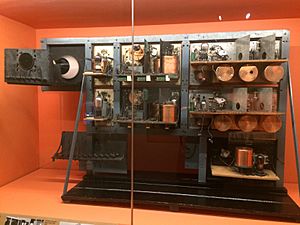
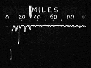
The signal from the transmitter also went to the receiver hut. This signal started the display on a cathode ray tube (CRT). When radio waves bounced off an object and returned, they created "blips" on the screen. Objects closer than about 8 kilometers (5 miles) could not be seen because the transmitted signal was too strong.
The receiver system amplified the weak reflected signals. The output went to the CRT screen. Operators measured the blips against a scale to find the distance to the target. Later, a "calibrator unit" was added, which put sharp blips every 16 kilometers (10 miles) on the display to help with measurement.
Measuring Distance and Direction
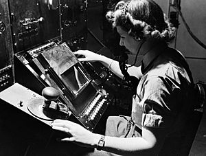
Finding a target's location was a multi-step process. First, the operator selected a set of receiver antennas. They would then adjust a special dial, called a "gonio," until the blip on the screen was at its smallest. This helped them find the direction of the target. The operator would then tell the plotter the distance and direction.
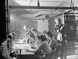
The plotter used large maps. They had a rotating ruler centered at the radar's location. When the operator called out an angle, the plotter turned the ruler to that angle and marked the distance. The distance given by the operator was the "slant range" (straight-line distance), not the distance over the ground. To find the ground distance, the altitude also had to be measured and calculated using simple math.
As the plotter worked, they would get updates, creating a "track" of the target's movement. "Track-tellers" then relayed this information by phone to the filter room in London. There, reports from many stations were combined into one overall view. Each track was given a number. This information was then sent to RAF Group and Section headquarters to help guide fighters.
Measuring Altitude
Chain Home could also estimate a target's altitude. The receiver antennas were arranged in a way that created several "lobes" or sensitive areas at different vertical angles. The main lobe was about 2.5 degrees above the horizon. This meant planes flying very low could sometimes escape detection.
To find altitude, the operator would switch to two antennas placed at different heights on one mast. By adjusting the gonio, they could find the vertical angle of the target. Using this angle and the slant range, the plotter could calculate the target's actual altitude and ground distance. This calculation also had to account for the Earth's curve.
Assessing Raids
CH operators also had to estimate how many planes were in a raid and what type they were. They could tell the overall size by how strong the signal was. They could also reduce the pulse length to get a clearer picture of individual planes within a group. This skill improved with operator experience.
The Fruit Machine
Operating a CH station needed many people: an operator in the transmitter hut, an operator and assistant in the receiver hut, and up to six assistants for plotting and phone calls.
To reduce the number of people needed, the "fruit machine" was invented. This was an electromechanical analogue computer. It took the gonio setting for direction and a dial setting for range. When the operator pushed a button, the fruit machine read these inputs. It also had built-in corrections for angle and altitude. It then calculated the target's altitude and ground position.
Later versions of the fruit machine could directly show the aircraft's position on a chart. This meant fewer people were needed at the station. The data could even be sent automatically over phone lines.
Detection and Jamming
Early German Detection
In 1939, German airships flew along Britain's coast to investigate the tall radio towers. German sources say they detected the 12-meter Chain Home signals and suspected they were radar.
After the Battle of Dunkirk in 1940, the British had to leave a mobile radar station in France. German experts were able to study it and understand how it worked. This early radar was not very good, so the Germans thought British radar systems were not very effective. They didn't realize how important the whole system of plotting and reporting was. This was a big mistake for them during the war.
Fighting Jamming
The British knew the Germans might try to interfere with their radar. So, they designed CH with features to prevent this. One way was the ability to operate on different frequencies. Another was the "Interference Rejection Unit" (IFRU), which helped block out unwanted signals.
A clever system was also built into the CH displays. The screen had two layers of material: a fast-reacting blue layer and a slower "afterglow" yellow layer. A yellow plastic sheet in front of the screen made the blue layer invisible. This meant that short, random jamming pulses would only show up on the fast blue layer and disappear quickly. The slower yellow layer would only show the "averaged" signal from real targets, making them visible. This is why many old radar screens were yellow.
German Jamming Attempts
When the Germans first tried jamming, they used a clever method. They sent out fake radar pulses that matched the timing of a specific CH station. This caused the CH operator to change their station's timing, which then affected other stations.
These jammers were set up in France in July 1940. But the British quickly developed ways to fight back. By the start of the Battle of Britain on July 10, the jamming was mostly defeated. The Germans had more advanced jamming systems, but they weren't ready until September. This allowed Chain Home to work without much trouble during the most important part of the Battle of Britain.
The German Luftwaffe knew about CH but didn't take it seriously enough. They thought radar would not have much effect because they had trouble getting their own radar information to pilots. But the British had solved this problem with the Dowding system.
The Germans did try to attack CH stations, but British engineers quickly repaired them. The Germans eventually gave up trying to attack CH directly. Because CH was allowed to operate freely, it gave the RAF a huge advantage. This is why Churchill said Chain Home won the Battle of Britain.
More Advanced Jamming
Later, in September 1941, the Germans activated a new jamming system that responded to CH's pulses. This meant the jammer would still work even if the CH station changed its timing. These systems could also create multiple fake returns, making it look like many aircraft were on the CH display.
However, CH operators quickly adapted. They started changing the pulse repetition frequency (PRF) of their transmitters randomly. This made the synchronized jamming signals "jitter" on the screen, allowing operators to tell them apart from real targets. An "Intentional Jitter Anti-Jamming Unit" (IJAJ) did this automatically.
Another upgrade, the "Anti-Jamming Black-Out" (AJBO) unit, helped block out unsynchronized pulses. It made short, sudden blips disappear from the display.
German Use of CH: Klein Heidelberg
The Germans also secretly used Chain Home for their own passive radar system called Klein Heidelberg. This system used CH's transmissions as its source. A series of antennas along the Channel coast acted as receivers. By comparing the time the signals arrived from a selected aircraft, they could figure out its range and direction. Since this system didn't send out any signals of its own, the Allies didn't know about it until they captured the stations in 1944.
Chain Home Sites
Radar site locations changed a lot during the war as technology improved. By 1945, there were over 100 radar sites in the UK. After the war, the ROTOR system aimed to organize this large network.
Below is a list of some Chain Home sites:
| Site | AMES No. |
Location | Region | Coordinates | Ref. |
|---|---|---|---|---|---|
| Bawdsey | Suffolk | TM3412038310 | |||
| Beachy Head | East Sussex | ||||
| Branscombe | Devon | SY1988 | |||
| Brenish | Western Isles | NA9910024250 | |||
| Bride | Isle of Man | NX4604 | |||
| Broadbay | Western Isles | NB5314034470 | |||
| Canewdon | Essex | TQ9094 | |||
| Castell Mawr | 67 | Llanrhystud | Ceredigion | SN5369 | |
| RAF Clee Hill | Shropshire | SO5900877942 | |||
| Dalby | Isle of Man | SC2141878536 | |||
| Danby Beacon | Danby | North Yorkshire | NZ732097 | ||
| Darsham | Suffolk | TM408718 | |||
| Dengie | Essex | TL9850701703 | |||
| Douglas Wood | Monikie | Angus | NO4862041515 | ||
| Dover (Swingate) | Kent | TR335429 | |||
| Downderry | Cornwall | ||||
| Drone Hill | Coldingham | Borders | NT8447066535 | ||
| Drytree | Goonhilly Downs | Cornwall | SW723218 | ||
| Dunkirk | Kent | TR076595 | |||
| Folly | Nolton | Pembrokeshire | SM858195 | ||
| Great Bromley | Essex | TM104265 | |||
| Greystone | 61 | County Down Northern Ireland | |||
| Hawks Tor | Plymouth | Devon | |||
| Hayscastle Cross | Pembrokeshire | SM920256 | |||
| Hillhead | Memsie | Aberdeenshire | NJ9430061700 | ||
| Kilkeel | 78 | County Down, Northern Ireland | |||
| Kilkenneth | Tiree | Argyll and Bute | NL9408045570 | ||
| Loth | Helmsdale | Sutherland | NC9590009600 | ||
| Netherbutton | Holm | Orkney | HY4621104396 | ||
| Nefyn | 66 | Gwynedd | SH2704037575 | ||
| Newchurch | Kent | TR0531 | |||
| North Cairn | 60 | Stranraer | Dumfries | NW97107074 | |
| Northam | Devon | SS4529 | |||
| Noss Hill: | Shetland Islands | HU3613015575 | |||
| Ottercops Moss | Otterburn | Northumberland | NY944896 | ||
| Pevensey | East Sussex | TQ644073 | |||
| Poling | West Sussex | TQ043052 | |||
| Port Mor | Tiree | Argyll and Bute | NL9442 | ||
| Ravenscar | North Yorkshire | ||||
| Renscombe Down | Dorset | ||||
| Rhuddlan | 65 | Denbighshire | SJ012764 | ||
| Ringstead | Ringstead Bay | Dorset | SY751817 | ||
| Rye | East Sussex | TQ968232 | |||
| St. Lawrence, Isle of Wight | Isle of Wight | SZ530760 | |||
| Saligo Bay | Islay | Argyll and Bute | NR2116066740 | ||
| Sango | Durness | Sutherland | NC4170067500 | ||
| Saxmundham | Suffolk | TM411720 | |||
| Scarlett | Isle of Man | SC2566 | |||
| Schoolhill | Porthlethen | Aberdeenshire | NO9086098180 | ||
| Sennen | Cornwall | SW376246 | |||
| Skaw | Unst | Shetland Islands | HP6634016805 | ||
| Southbourne | Dorset | SZ1591 | |||
| Staxton Wold | North Yorkshire | TA023778 | |||
| Stenigot | Louth | Lincolnshire | TF256827 | ||
| Stoke Holy Cross | Norfolk | TG257028 | |||
| Tannach | Wick | Caithness | ND3200046900 | ||
| Tower | 64 | Blackpool | Lancashire | SD306357 | |
| Trelanvean | Goonhilly Downs | Cornwall | SW762193 | ||
| Trerew | Newquay | Cornwall | SW812585 | ||
| Ventnor | Isle of Wight | SZ568785 | |||
| Warren | Pembrokeshire | SR9397 | |||
| RAF West Beckham | 32 | West Beckham | Norfolk | TG1402138869 | |
| West Prawle | Devon | SX771374 | |||
| Westcliffe | Kent | ||||
| Whale Head | Sanday | Orkney Islands | HY7590546125 | ||
| Worth Matravers | Swanage | Dorset | SY967777 | ||
| Wylfa | 76 | Isle of Anglesey | SH3522093385 |
See Also
- History of radar
- Battle of the Beams
- Chain Home Low
- Ground-controlled interception
- ROTOR
- RAF Air Defence Radar Museum
 | Misty Copeland |
 | Raven Wilkinson |
 | Debra Austin |
 | Aesha Ash |


