
AMES Type 7 facts for kids
_radar_installation_at_RAF_Sopley,_Hampshire,_1945._CH15188.jpg)
Type 7 radar antenna at RAF Sopley in 1945. The happidrome visible in the background.
|
|
| Country of origin | UK |
|---|---|
| Manufacturer | Marconi |
| Introduced | 1941 |
| No. built | ~33 |
| Type | Ground-controlled interception |
| Frequency | 209 MHz (1.5 m, VHF), later 193 and 200 MHz |
| PRF | 250 to 540 pps |
| Beamwidth | 15° |
| Pulsewidth | 3.6, 5 or 8 µs |
| RPM | 0.5 to 8 rpm |
| Range | 220 nmi (410 km) theoretical, ~90 mi (140 km) in practice |
| Altitude | 80,000 ft (24,000 m) |
| Diameter | 30 by 25 ft (9.1 by 7.6 m) |
| Azimuth | 360º |
| Elevation | 2.5 to 20º |
| Precision | ~1.5° in azimuth, 500 m in elevation |
| Power | 80-100 kW |
| Other Names | Final GCI, happidrome, SCR-527 |
| Related | AMES Type 8, AMES Type 15 |
The AMES Type 7 was a special kind of radar system. It was used by the Royal Air Force (RAF) during World War II. This radar was also known as the Final GCI. GCI stands for "Ground Controlled Interception."
The Type 7 was a big step forward for radar technology. It gave a full 360-degree view of the sky around the radar station. It could see planes up to about 90 miles (140 km) away. This meant that controllers on the ground could guide fighter planes directly from the radar screen. This was a new and very effective way to intercept enemy aircraft.
Older radar systems, like Chain Home, could only track one target at a time. To guide a fighter, information had to be sent between many stations. This made the process slow and not very accurate. A smart scientist named Robert Hanbury Brown realized this problem in 1939. He suggested that a radar should spin its antenna and display. This would create a full picture of the sky, called a plan position indicator (PPI). This new method would make guiding planes much more precise.
The first test of this idea was with the AMES Type 8 radar. It was a modified version of an existing radar. When the Type 8 was first used in late 1940, it worked very well. The lessons learned from the Type 8 helped create the Type 7 design. The Type 7 started being used in late 1941. From 1942, the radar stations were built into permanent buildings called "happidromes." The RAF slowly built up a network of 33 Type 7 stations by 1944. The United States also tried to copy it, calling their version the SCR-527.
After World War II ended, many radars were put away. But when the Soviet Union tested its first atomic bomb in 1949, the UK realized it needed strong defenses again. Many Type 7 radars were brought back, updated, and placed in bomb-proof buildings. This was part of a big project called ROTOR. Later, a more powerful radar, the AMES Type 80, replaced most Type 7s. However, some Type 7s stayed as backups or to fill gaps until the 1960s.
How Radar Developed
Early Radar: Chain Home

In 1935, a group of scientists asked Robert Watson-Watt about a German "death ray" using radio waves. Watt and his assistant, Arnold Frederic Wilkins, found that a death ray was not possible. But Wilkins remembered that aircraft could affect radio signals. They suggested using radio waves to detect planes instead. This idea was quickly tested in the Daventry Experiment. Watt was very excited, saying, "Britain has become an island again!"
Watt wanted to build a radar system very quickly. He believed it was better to have a "third best" system now than wait for the "best" one later. His idea was to use modified storm locators. These locators found storms by measuring radio signals from lightning. For radar, a powerful radio transmitter sent out signals. Reflections from aircraft were picked up by separate antennas. These early systems were called Chain Home (CH). They were simple but effective. By 1939, a full network of CH radars was ready for battle.
CH radars were placed along the coast to give early warnings. They could spot German planes forming up over France. But they didn't cover the land very well. Over Britain, the Royal Observer Corps (ROC) tracked planes using binoculars. All this information was sent by phone to RAF Fighter Command. This system was called the Dowding system. It helped guide fighters, but it was slow and not perfectly accurate.
Pilots soon found that flying low could help them avoid CH radar. The Germans also learned this. To fix this, the British Army had a radar called Coast Defence (CD Mk. I). It was designed to spot ships but also worked well against low-flying planes. Watt ordered 24 of these, calling them Chain Home Low (CHL). CHL radars used a spinning antenna to scan the sky. This made them simpler to use than the CH system.
New Ideas: AI, PPI, and GCI

The Dowding system had some problems. Reports from different radars and observers were not always the same. Also, it took time for information to reach the fighter pilots. This meant the information was always a bit old and not perfectly accurate. The system was usually off by about 5 miles (8.0 km). This was okay for daytime fights, but at night, pilots couldn't see far. They needed a more precise way to find targets.
As early as 1936, people thought Germany might start bombing at night. Watt believed the best solution was a radar small enough to fit on an aircraft. This radar would have a range of about 5 miles. The CH system would get the fighter close, and then the plane's own radar would take over. This led to the AI Mk. IV radar, which started testing in 1940.
In 1939, Robert Hanbury Brown studied how to intercept planes. He showed that the delays in the Dowding system made it hard to use the AI radars effectively at night. He said the only way to fix this was for radar operators to control the fighters directly. This meant cutting out the middle-men.
He imagined a radar system where the antenna and the display screen spun together. As the radar sent out a signal, a line would appear on the screen in the direction the radar was pointing. When a signal bounced back from a plane, it would make a bright dot on the screen. The screen would use a special material that kept the dots visible for a while. Hanbury Brown called this the plan position indicator (PPI).
The PPI display would show bright dots representing all aircraft around the radar station. It would look like a map of the sky. An operator could then see where the planes were and guide fighters to them directly. Any errors in the radar would affect both the fighter and the target equally. This was much better than the old system.
At first, the RAF was busy getting CH and CHL radars working. But by 1940, things improved. A team at the Telecommunications Research Establishment (TRE) successfully made a CHL antenna spin. They also combined the transmit and receive antennas. The next month, they tested the first PPI display. It worked by connecting the display to the antenna's motor.
Temporary Solutions
When the Battle of Britain ended, Germany started bombing Britain at night. This was called The Blitz. The RAF found that Hanbury Brown's predictions were true. Night fighters often flew around without finding any targets. The PPI would solve this, but it wasn't ready yet. So, the TRE worked on temporary solutions.
One idea was tested at RAF Foreness Point. This station could see German bombers laying mines in the Thames River. These bombers flew very low to avoid detection. Foreness Point had a CHL radar to spot them.
In 1940, they tried guiding fighters directly. The CHL radar would find a target and track it. A controller would then guide a night fighter to fly into the radar's beam. Both the fighter and the bomber would appear on the CHL display. The CHL operator would then tell the pilot to turn left or right to stay on target. As the fighter got closer, its own radar would pick up the bomber. This system worked, but it was slow and difficult to use.
The Type 8 Radar
The CHL antennas were very large. They were originally made to track slow ships. But the Army had smaller radars for guiding anti-aircraft artillery, called the GL Mk. II radar. The AMES team used the same spinning display idea with the smaller Mk. II receiver antenna. They called this the AMES Type 8. The first Type 8 started working on Christmas Day 1940 at RAF Sopley. It was a big success, guiding 9 out of 10 test interceptions. The old Dowding system only managed about 1 in 10.
More Type 8 systems were quickly ordered. By January 1941, five more were ready. With these units, night interception rates improved quickly. They roughly doubled each month until May. Then, the German air force stopped the Blitz to focus on the Soviet Union.
The Type 7 Radar Arrives
While the Foreness and Sopley tests were happening, the lessons learned helped design a special GCI radar. A meeting in June 1941 outlined the new system. The Type 8 could only guide one interception at a time. The "final GCI" needed to guide many. The new design included several key features:
- The antenna and display would spin automatically and continuously.
- The radar would also be able to measure how high planes were flying.
- It would use IFF (Identification Friend or Foe) to tell friendly planes from enemy ones.
- The antennas would be far from the operations rooms. The electronics would be at the antenna site.
- The operations rooms would handle everything: tracking, calculating intercepts, and talking to fighters.
It became clear that the GCI radar wouldn't be ready until late 1941 or early 1942. So, the Type 8s were upgraded to bridge the gap. The original Type 8s were called "mobile" (Stage 1). They were updated with new antennas and motors, becoming "transportable" (Stage 2). These were bigger and took 12 hours to set up. When the new GCI systems arrived in Britain, the transportable Type 8s would be used overseas. Stage 3 was the "final GCI," the fixed-site Type 7 systems in Britain.
Deployment Challenges
In January 1941, the plan was to build 47 GCI stations by June 1941. But this proved impossible. The spinning gear was harder to build than expected. Only eleven more mobile sets were ready by July. Even with delays, more units were ordered.
After the Blitz ended in spring 1941, German attacks on Britain decreased. Most attacks were by single planes or small raids. To deal with these, PPI displays were added to Chain Home Low radars. This helped cover the approaches to Britain.
The final design for the GCI was ready on June 7, 1941. It was officially named the Type 7. It was expected to take six months to build. Fighter Command asked for 21 fixed stations. They wanted 12 of them ready by April 1942 and the rest by June.
But German attacks kept decreasing. The Type 7 deployment became less urgent. The TRE focused on other projects. A meeting in April 1942 reduced the deployment to 13 systems by November 1942. Then, it was cut to only seven systems by the end of 1942. However, after concerns from Fighter Command, the order was expanded again to 32 stations. Two of them, RAF Durrington and Sopley, were already finished.
Durrington became operational on June 9, 1942. It guided RAF night fighters to shoot down a German bomber the next night. But the small PPI display was a problem. Only one operator could see it well enough to plot an interception. By October 1943, 20 of the 21 fixed stations were installed. But guiding multiple interceptions was still difficult.
Dealing with Jamming: Window and Düppel
During 1942, a new countermeasure called "Window" was developed. It was strips of aluminum foil that bombers dropped. These strips created many false signals on German radars, making it hard to find the real planes.
There was a big debate in the RAF about using Window. Fighter Command worried that Germany would copy it. This could make it impossible to stop night attacks on the UK. The decision to use Window was made and changed several times. It was finally allowed when Fighter Command got new radars that weren't affected by it.
Ironically, Germany had their own version called Düppel. They hadn't used it because they thought the RAF would copy it. For months, both sides knew about this technology but didn't use it. Eventually, Hermann Göring ordered all information on Düppel destroyed.
After the British used Window, Germany started making their own version. They used Düppel for the first time on October 7, 1943. A huge raid appeared on radar screens, with hundreds of planes. It was almost impossible to guide night fighters because of all the clutter. The IFF signals were also jammed.
But operators quickly learned to deal with Düppel. They started to recognize patterns in the false signals. On November 15, a raid on Plymouth was tracked successfully despite a lot of Düppel.
Operation Steinbock and Later War Efforts
German use of Düppel in small raids helped British radar operators prepare for Operation Steinbock in early 1944. This was a German bombing campaign. By May 1944, all 33 Type 7 radars were working.
RAF night fighter operations during this time were not very effective. German planes used Düppel and other jammers. More importantly, they flew very low for most of their journey. They only climbed when they got close to their target. This meant the Type 7s could only see them for short periods. Luckily for Britain, the German air force was much weaker by then.
Concerns about jamming led to new radar developments. In 1941, some Type 8s were converted to use higher frequencies (250-300 MHz). This was to avoid jamming at 1.5 meters. Only three were finished by March 1944. A more serious effort was the AMES Type 11, which used 600 MHz. Six were ordered in January 1942 and installed at Chain Home Low sites. In October 1943, they moved to Type 7 sites as backups. But they had gaps in their coverage and were still affected by Düppel.
A better solution came in June 1943. This was the AMES Type 14, a microwave radar that used 10 cm wavelengths. It was based on the AMES Type 13 height-finding radar. These were meant to be installed with a Type 13 to create the AMES Type 21. The first Type 21 was installed in early 1944 at RAF Sandwich. By June 1944, most GCI stations had a Type 21 along with their Type 7.
By May 1944, the UK had 208 early warning stations and 33 GCI stations. But by November 1943, some stations were already being shut down. After the D-Day invasions, the Allies learned about a German system called Klein Heidelberg. This system tracked Allied bombers using Chain Home signals. So, CH stations were turned off when bombers were on missions. By 1945, many radars were moved from the UK to Europe to support operations there.
After the War
In August 1944, the RAF started planning for after the war. They wanted to keep some radar stations around London. The rest of the country would have fewer radars, fighters, and anti-aircraft guns. This plan was changed several times.
A report in late 1945, called the Cherry Report, looked at the new Soviet Tu-4 Bull bomber. This bomber could reach the UK and was fast enough to escape the Type 7s. The report suggested sending information from many stations electronically to "Master GCI Stations." This would give operators a much bigger view of the sky. This was meant to be a temporary solution until a radar with a 250-mile range could be built.
The government thought another war was at least ten years away. They wanted to save money and manpower. They also knew radar technology was improving fast. So, they decided to reduce operations. Only seven GCI stations and three CH stations remained active. Equipment from other stations was moved to these few sites. Four Master GCI stations were set up at Sopley, Trimley Heath, Neatishead, and Patrington.
The ROTOR Project
The Berlin Blockade in July 1948 raised concerns about a new war. A report in March 1949 found that the radar stations were in bad shape. Many were damaged by weather or vandalized. Also, the UK didn't have enough fighters or anti-aircraft units. This became very urgent when the Soviet Union tested its first atomic bomb in August 1949. A new goal was set: RAF Fighter Command's main job was to defend Great Britain.
This led to the ROTOR project. The plan was to reactivate and upgrade existing radar sites. Then, they would replace them with much better new radars. Existing GCI stations would get improved antennas, better electronics, and updated displays. They would also get four Type 13s for height measuring and two Type 14s for anti-jamming. The old "happidrome" buildings would be upgraded to underground control centers. These centers could survive nearby bomb blasts.
This "Stage 1" system was supposed to be finished in the London area quickly. Then, it would expand to the whole country by mid-1953. But this schedule was too ambitious. Delays continued, and the network wasn't ready until 1955.
Meanwhile, the Radar Research Establishment developed an experimental radar called Green Garlic. This radar could meet most of the needs for the new replacement radars, and it would be ready years earlier. This helped ease the pressure on the upgrade process. By the end of 1953, most of the Type 7 upgrades were done.
The Type 80 Arrives

Work on Green Garlic continued to be successful. The first working units, now called AMES Type 80, were installed in 1953. This was years ahead of schedule. A new version, Mark III, was even better. It had such good resolution that it could handle the GCI role too. These units also had an improved range of 250 miles (400 km). This meant they didn't need the Master Control Centers anymore. They could handle interceptions directly from the Type 80's display over a much larger area.
The Mark III Type 80s became operational in 1955. At this point, the Type 7s were no longer essential. A few Type 7 stations were kept in the new system. They mostly filled gaps between the Type 80 stations. For this role, they were upgraded again. They kept the ROTOR electronics but got a new antenna. This antenna greatly improved their horizontal accuracy. As part of this change, they lost the ability to measure height. But this was okay because separate height finder radars were now used.
Retirement
The last Type 7 radars were likely removed from service in the late 1950s or early 1960s. They are not mentioned in records from the 1960s onwards. They were no longer in use when the Linesman/Mediator network was built in the late 1960s.
How the Type 7 Worked
Type 7 stations usually had two main parts. The antenna and its "Radar Well" were in one place. The "Operations Room" was in a separate building, usually a few hundred meters away. The operations rooms were nicknamed "happidromes." This name came from a popular BBC Radio show called Happidrome. If the operations room was far from the radar, it was called a "remote" installation.
Antenna System

The Type 7 used many small antennas called dipole antennas. Each was about 150 centimetres (59 in) long. They were arranged in rows, with eight antennas in each horizontal row. When one row was powered, it created a narrow beam horizontally (about 15 degrees wide). It was wide vertically. Eight such rows were stacked on top of each other. A wire mesh behind the antennas reflected the signal forward. The whole antenna had four rows of eight dipoles, making 32 parts in total.
The rows of dipoles were grouped. Two rows were in the "top array," and one each in the "middle array" and "bottom array." All three could be connected to make one large antenna. This antenna was very focused both horizontally and vertically. It was used for long-distance detection. More often, one of the lower arrays was used separately for height finding. By connecting them in different ways, the antenna could form several "lobes" of sensitivity. These lobes helped measure the vertical angle (height) of a target.
The antennas and reflector were mounted on a large steel frame. A tall steel pole in the middle supported the frame and held the wiring. The antenna hung from a large bearing at the top of this pole. The whole system was 54 feet (16 m) wide and 30 feet (9.1 m) high. It weighed about 20 long tons (20 t).
A 15-horsepower DC motor spun the antenna. It was connected by a chain drive at the base of the pole. A larger AC motor powered the DC motor. A special system kept the spinning speed steady, even in windy conditions. The antenna could spin in either direction. It had different speeds, but 6 revolutions per minute (RPM) was the most common.
The radar's transmitter and receiver electronics were in a concrete room underground, called the Radar Well. The signal went to the antenna through a switch system. This system protected the receivers from being overloaded during the powerful transmit pulse. The antenna hut also had a display for tuning the system.
The location of the antenna was very important. The height-finding system used the reflection of the radar beam off the ground. For this to work well, the ground in front of the antenna had to be very flat. The best sites were natural bowl-shaped areas.
If other radars were nearby, they would get their timing signals from the Type 7. This made sure they didn't transmit at the same time, which would cause interference.
Plotting and Reporting
The happidromes were large buildings, about 150 by 40 feet (46 by 12 m). They often had a single-level section for things like washrooms and generators. The two-story section held the main working area, called the Reporting Hall.
The PPI and height finder "Intercept Cabins" were arranged in a C-shape on the main floor of the Hall. They were slightly raised. Each cabin had a PPI display, a height finder display, a plotting table for the fighter director, and a recording station. Some happidromes had up to a dozen PPI stations. But only a few, usually two or three, were in the main Hall. These were called red, green, and yellow.
In the open area in the center of the C-shape, sunk into the ground, were "plotters." They would take reports from the cabins and place wooden markers on a large map. This helped them track the battle. The markers showed information like altitude and how many planes were in a group. Other plotters received information from fighter bases. They put markers on their own map to show planes outside their area. A third group combined all this information onto a "General Situation Map" in the center of the Hall. At the back of the Hall was a "Tote Board." It showed the status of fighter squadrons.
Above the cabins were offices with large glass windows. These offices had a good view of the Hall floor. They included offices for the Chief Controller, the Fighter Marshal, and the Anti-Aircraft Commander. All these offices also had their own PPI displays. The Chief Controller watched the General Situation Map. They could choose available aircraft from the tote board and assign them to intercept targets.
Any of the cabins could be given the task of intercepting a target. They would then guide their assigned fighter. The radio operations room handled general communications with aircraft not under direct control of the intercept cabins. These operators mainly helped fighters get to and from their airfields. Some happidromes also had a "tellers room." Here, tracks were developed to report to other stations or headquarters.
To make work easier, ROTOR upgrades added skiatrons. These projected the PPI display directly onto the map boards. Operators could then place their markers right on top of the dark spots on the map. Tracking a plane was as simple as updating the marker's position at set times. Small arrows showed where the plane had been.
To communicate with the outside world, happidromes had their own telephone systems. They also had VHF and UHF radios to talk to aircraft. The radio antennas were located far away, sometimes over a mile. This prevented interference from the radar.
ROTOR Upgrades
The Mark 2 and 3 upgrades mainly improved the electronics. The most important change was an increase in power. The radar could now transmit up to 500 kilowatts. This was five times more powerful than the original models. The receivers were also improved, making them less noisy.
For the Mark 4 and 5 upgrades, the antenna was made wider and shorter. It became 64 feet (20 m) wide and 11 feet (3.4 m) tall. It was still mounted on the same pole. The extra width allowed for 12 dipoles in each row, up from eight. The number of vertical rows was reduced to four. This made the horizontal beam much narrower, from 15 to 3.6 degrees. This helped the radar see planes flying close together more clearly. As part of this change, the ability to connect the rows in different ways was removed. Height finding was now done by separate AMES Type 13 height finding radars.
The Mark 3 and 5 versions were "remote reading." This meant they had extra equipment to send their signals over coaxial cable up to about 2 miles (3.2 km). The displays were located at a Type 80 station. This allowed these stations to be used as backups if the Type 80 was jammed or attacked. Both were also equipped with IFF Mark 10. This IFF system was not mounted on the Type 7 antenna. Instead, it was adapted to fit into the AMES Type 14 GCI radar's mount. This unit was called AMES Type 79. It spun with the Type 7 and used its main trigger signal. This prevented it from sending its IFF pulses at the same time as the radar.
Performance
How far the system could see depended on the plane's altitude. For a bomber-sized target, it could see about 10 miles (16 km) at 500 feet (150 m). But it could see up to 90 miles (140 km) at 20,000 feet (6,100 m). These ranges were when all the dipoles were used together. When used for height finding, the ranges were shorter. For targets between 2.5 and 20 degrees above the horizon, height finding was accurate to about 500 feet (150 m). The direction accuracy was about 1.5 degrees.
The Mark 4 and 5 upgrades greatly improved performance. They could see a Meteor NF.11 jet at the horizon up to about 240 miles (390 km) away. It also had much better vertical coverage. It could see the same target about 70 miles (110 km) away at 10 degrees above the horizon.
See Also
- AMES Type 8
- AMES Type 15
- Chain Home
- Ground-controlled interception
- ROTOR
Images for kids
-
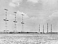
The Poling Chain Home installation in 1945. The tall towers on the left sent out radio signals. The smaller towers on the right received them.
-
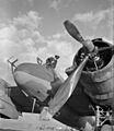
The AI Mk. IV radar was meant to see planes up to 5 miles away, but it often struggled to do so.
-
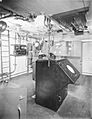
The Radar Well under RAF Sopley. This underground room held the radar's transmitter and receiver.
-
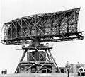
The Type 80's huge antenna could see very far and was very accurate. It combined early warning and guiding fighters.
