High-frequency direction finding facts for kids
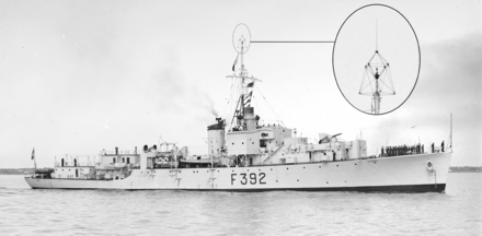
High-frequency direction finding, often called HF/DF or its nickname huff-duff, was a special type of radio direction finder (RDF) used during World War II. It helped locate radio signals.
High frequency (HF) refers to a type of radio signal that can travel very long distances. This was perfect for things like U-boats (German submarines) communicating with their headquarters on land. Huff-duff was mainly used to find enemy radios when they sent messages. It also helped friendly aircraft find their way. Even today, the basic idea is still used in spying on radio signals.
Older radio direction finders needed an operator to physically turn an antenna. They would listen for the signal to get stronger or weaker. This took a long time, sometimes a minute or more. But huff-duff systems used several antennas that picked up the signal from slightly different spots. These small differences were then shown instantly on a screen called an oscilloscope. This meant huff-duff could catch very quick signals, like the short messages sent by U-boats.
The system was first developed by Robert Watson-Watt in 1926. He originally wanted to use it to find lightning strikes. Its use for military intelligence didn't start until the late 1930s. During the early part of World War II, huff-duff units were in high demand. They were used by the RAF Fighter Command to help control fighter planes during the Battle of Britain. Ground-based units also helped the Royal Navy find U-boats. Between 1942 and 1944, smaller huff-duff units became common on Royal Navy ships. It's believed that huff-duff helped sink about 24% of all U-boats during the war.
This technology is also known by other names, like Cathode-Ray Direction Finding (CRDF) or Watson-Watt DF.
Contents
History of Radio Direction Finding
Before Huff-Duff
Finding the direction of radio signals was a common technique even before World War I. It was used to help ships and planes navigate. The basic idea used a loop antenna, which was simply a circular wire. When this loop was turned so it was exactly at right angles to a radio signal, the signal would cancel itself out. This created a sudden drop in sound, called a "null."
Early systems had an antenna that the operator had to turn by hand. The operator would find a radio station and then turn the antenna until the signal disappeared. This meant the antenna was now at a right angle to the radio station. But it could be on either side of the antenna. By taking several measurements, or using other navigation tools, they could figure out the exact direction.
In 1907, Ettore Bellini and Alessandro Tosi created a better system. Instead of one loop antenna, they used two antennas placed at right angles to each other. The signals from these antennas went to special coils. These coils created a magnetic field. A rotating coil, called a "search coil," picked up this magnetic field. The strongest signal was found when the search coil lined up with the magnetic field. This meant the antennas themselves didn't need to move. The Bellini–Tosi direction finder (B-T) was widely used on ships.
All these early devices took time to use. The radio operator first had to find the signal. Then, they would turn the antennas or controls to find the strongest or weakest signal. This was hard with short signals, like Morse code, or weak signals. It often took about a minute to get a good reading.
Before World War II, some engineers tried to make the B-T system automatic. Maurice Deloraine and Henri Busignies developed a system that spun the search coil very fast. A light on a display would flash when it was in the right direction. When spinning fast, the flashes looked like a single dot that showed the direction.
Watson-Watt's Invention
People had known for a long time that lightning creates radio signals. These signals are very strong, especially in the longwave range, which was used for long-distance naval communication. Robert Watson-Watt showed that by measuring these radio signals, you could track thunderstorms. This could give an early warning to pilots and ships. He even detected thunderstorms over Africa, about 2,500 kilometers (1,550 miles) away.
However, lightning strikes lasted such a short time that traditional radio direction finders couldn't figure out the direction before they vanished. In 1916, Watt suggested using a cathode ray tube (CRT) screen to show the direction instead of mechanical parts. But he couldn't test this idea at the time.
In 1924, Watt moved to a new research site in Ditton Park, England. This site already had the National Physical Laboratory (NPL) Radio Section. Watt studied how radio signals travel through the air. The NPL had two important tools: an Adcock antenna and a modern oscilloscope.
The Adcock antenna used four tall poles that acted like two virtual loop antennas. By comparing the signals from these virtual loops, they could find the direction of a signal. This antenna was good because it didn't pick up signals that bounced down from the sky, which could cause errors.
Watt's goal was still to find the exact location of individual lightning strikes. The lab got a new oscilloscope from Bell Labs. In 1926, Watt and Jock Herd connected amplifiers from the Adcock antenna to the oscilloscope's X and Y channels. Just as they hoped, the radio signal created a pattern on the screen that showed the direction of the lightning strike. The screen's glow lasted long enough for the operator to measure it.
Watt and Herd wrote a detailed paper about their system in 1926. They called it an "instantaneous direct-reading radiogoniometer." They said it could find the direction of signals lasting as little as 0.001 seconds. Even though they showed it publicly, the idea remained mostly unknown outside the UK. This allowed it to be developed in secret for military use.
Battle of Britain
Before the Battle of Britain, Chain Home (CH) radar stations were built along the coast. This gave the earliest warning of enemy planes. But inland areas of Britain didn't have radar coverage. They relied on the Observer Corps to spot planes visually. The Observer Corps could track large groups of planes, but fighter planes were too small and high to be easily identified. The entire Dowding system of air control needed to know where its own fighters were.
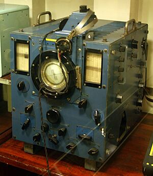
The quick solution was to use huff-duff stations to listen to the fighter planes' radios. Every Sector Control, which managed several fighter squadrons, had a huff-duff receiver. Two other smaller stations were placed about 30 miles (48 km) away. These stations would listen for broadcasts from the fighters. By comparing the angles from all three stations, they could figure out the fighters' exact location. This information was then sent to the control rooms. By comparing the enemy's position (from the Observer Corps) with their own fighters' positions (from huff-duff), commanders could direct fighters to intercept the enemy.
To help with this, a system called "pip-squeak" was put on some fighters. At least two planes in each section (a group of planes) had it. Pip-squeak automatically sent out a steady tone for 14 seconds every minute. This gave huff-duff operators plenty of time to track the signal. The only downside was that it tied up the aircraft's radio while it was broadcasting.
The need for these DF sets was so urgent that the Air Ministry couldn't supply enough at first. But in 1938, simulated battles showed how useful the system was. The Ministry then provided older Bellini-Tosi systems, promising to replace them with CRT versions as soon as possible. By 1940, these newer systems were in place at all 29 Fighter Command "sectors." They played a big part in winning the Battle of Britain.
Battle of the Atlantic
Along with sonar (called "ASDIC"), intelligence from breaking German codes (called Ultra), and radar, "Huff-Duff" was a very important tool for the Allies. It helped them find German U-boats and commerce raiders during the Battle of the Atlantic.
The German Navy (Kriegsmarine) knew that radio direction finders could locate their ships when they sent messages. So, they created a system to turn regular messages into very short ones. These "kurzsignale" messages were then encoded with the Enigma machine for security. An experienced radio operator could send a typical message in about 20 seconds. If the UK had only used the older B-T systems, which was all the Germans knew about, finding these quick transmissions would have been very hard. But with huff-duff, these messages were long enough to easily measure.
At first, the UK's detection system used several shore stations in Britain and the North Atlantic. They would work together to find locations. But the distances to U-boats in the Atlantic were so great that the fixes were not very accurate. In 1944, a new plan was made. Groups of five shore-based DF stations were built close together. The directions from each of the five stations could then be averaged to get a more reliable direction. Four such groups were set up in Britain. Operators were also asked to rate how reliable their readings were. This way, less stable readings were given less importance.
It was much harder to use huff-duff on ships because the ship's metal structure interfered with radio signals. However, these problems were solved by a Polish engineer named Wacław Struszyński. As ships got huff-duff, a complex series of measurements was done. This helped figure out how the ship's structure affected the signals. Operators were given cards that showed the corrections needed for different radio frequencies. By 1942, more cathode ray tubes became available, so more huff-duff sets could be made.
Newer sets could also automatically scan different frequencies. They would sound an alarm when any transmissions were detected. Operators could then quickly fine-tune the signal before it disappeared. These sets were put on convoy escort ships. This allowed them to get directions to U-boats transmitting from far away, even beyond radar range. This meant "hunter-killer" ships and aircraft could be sent quickly towards the U-boat. The U-boat could then be found by radar if it was on the surface, or by ASDIC (sonar) if it was underwater.
From August 1944, Germany was working on the Kurier system. This system would send an entire short message in a super-fast burst transmission that lasted less than half a second. This would have been too short to locate or decrypt. But the system was not ready by the end of the war.
How Huff-Duff Works
The main idea of the huff-duff system is to send signals from two antennas to the X and Y channels of an oscilloscope screen. For ground stations, the Y channel usually showed north/south. For ships, it lined up with the ship's front/back direction. The X channel then showed east/west, or side-to-side (port/starboard) on a ship.
The dot on the oscilloscope screen shows the immediate strength and direction of the radio signal. Radio signals are waves, so the signal changes very quickly. If you only look at the signal from one antenna (say, the Y channel), the dot would move up and down so fast it would look like a straight vertical line. When the signal from the second antenna is added, the dot moves in both X and Y directions at the same time. This makes the line diagonal. Because the radio signal has a certain wavelength, the signal reaches different parts of the antenna at slightly different times. This makes the line on the screen turn into an oval shape, or Lissajous curve. This oval is rotated so its longest part points in the direction of the signal. For example, if a signal came from the northeast, the oval would lie along the 45-degree line on the screen.
This still leaves a problem: is the signal coming from the northeast or the southwest? The oval looks the same in both directions. To solve this, a separate "sense aerial" was added. This antenna picked up signals from all directions. It was placed a fixed distance from the main antennas. When its signal was mixed in, it would strongly block the signal when the phase was in the opposite direction. This signal was sent to the brightness control of the oscilloscope. It made the display disappear when the signals were out of phase. By connecting the sense aerial to one of the main antennas (like the north/south channel), the display would disappear if the signal was coming from the lower half of the screen. This showed that the signal must be coming from the north. So, the only possible direction would be the northeast.
The signals picked up by the antennas are very weak and at high frequencies. So, they are first amplified by two identical radio receivers. These two receivers must be perfectly balanced. If one amplifies more than the other, the direction shown on the screen will be wrong. To balance them, most systems had a "test loop" that sent out a signal from a known direction.
For huff-duff systems on ships, the ship's metal structure caused serious interference. This was especially true for the phase of the signals as they moved around the metal parts. To fix this, the ship would anchor, and another ship would broadcast a test signal from about a mile away. The resulting signals were recorded on a calibration sheet. This process was repeated with the broadcast ship at different locations. The calibration was different for different radio wavelengths and directions. Creating a full set of these sheets for each ship took a lot of work.
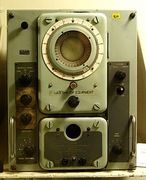
Naval units, like the common HF4 set, had a rotating plastic plate with a line, called a "cursor." This helped measure the angle. It could be hard to see the exact ends of the oval on the screen. By lining up the cursor with the peaks of the oval, it became simple. Marks on the cursor also helped measure the width of the display.
See also
- Operation RAFTER – a way to remotely check if a radio receiver is tuned to a certain frequency
- Wullenweber - a very large circular antenna array, sometimes called "Elephant Cage"
- Y service
 | Kyle Baker |
 | Joseph Yoakum |
 | Laura Wheeler Waring |
 | Henry Ossawa Tanner |


