History of radar facts for kids
The history of radar is about how we learned to use radio waves to find objects. Radar stands for radio detection and ranging. This means it uses radio waves to figure out if something is there and how far away it is.
Scientists like Heinrich Hertz in the late 1800s showed that radio waves bounce off metal objects. This idea came from James Clerk Maxwell's work on electromagnetism. But it took a while for people to build machines that could actually use this idea.
In the early 1900s, a German inventor named Christian Hülsmeyer built a simple device to detect ships in fog. It helped prevent collisions. But it couldn't tell you how far away the ship was.
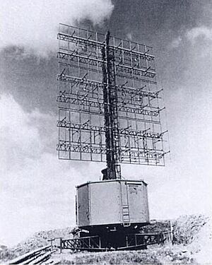
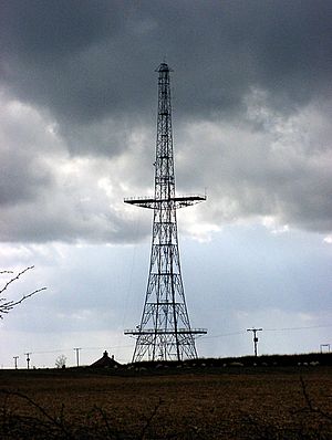
Real radar systems, like the British Chain Home warning system, were developed over the next 20 years. These systems could tell you both the direction and distance of objects.
A big step was learning to send out short bursts, or "pulses," of radio energy. By timing how long it took for a pulse to bounce back, scientists could figure out the distance. The direction of the antenna showed where the object was. Together, this gave a "fix" on the target's location.
Between 1934 and 1939, eight countries secretly developed these systems: the United Kingdom, Germany, the United States, the USSR, Japan, the Netherlands, France, and Italy. Britain also shared its knowledge with the United States and four Commonwealth countries (Australia, Canada, New Zealand, South Africa). The word RADAR was created in 1939 by the United States Signal Corps.
Radar technology grew very fast during World War II. It was a major reason the Allies won. A key invention was the magnetron in the UK. This allowed smaller radar systems that could see very fine details. By the end of the war, many countries had different types of radar for land, sea, and air.
After the war, radar was used for many things beyond the military. These include civil aviation, ship navigation, radar guns for police, meteorology (weather forecasting), and even medicine. New inventions like the travelling wave tube and phased array radars, along with faster computers, made radar even better.
Contents
Why Radar Matters
Some people say radar didn't add much new scientific theory. They argue that the basic ideas were already known from Maxwell and Hertz. So, radar was more about engineering and making things work. Maurice Ponte, a French radar developer, said that the main idea of radar was already known to physicists. He felt that the real achievement was building working machines.
But others point out how much radar changed the world. Many believe it helped the Allies win World War II even more than the atomic bomb. Robert Buderi, a historian, says radar led to many modern technologies. For example:
- Astronomers can map distant planets.
- Doctors can see inside the body.
- Meteorologists can measure rain far away.
- Air travel is much safer.
- Computers are everywhere.
- People can cook food quickly in a microwave oven (which used to be called a radar range).
Later, radar was also used in scientific tools like weather radar and radar astronomy.
Early Inventors
Heinrich Hertz
From 1886 to 1888, German physicist Heinrich Hertz proved that electromagnetic waves (like radio waves) exist. These waves had been predicted by Scottish physicist James Clerk Maxwell. In 1887, Hertz found that these waves could travel through different materials and bounce off metal surfaces. He showed that radio waves act like visible light because they can be reflected, bent, and polarized.
Guglielmo Marconi
Guglielmo Marconi, a radio pioneer, noticed radio waves bouncing back to his transmitter in 1899. This happened during experiments with radio beacons. In 1916, he and British engineer Charles Samuel Franklin used short-waves in their tests, which was important for radar. Marconi shared his findings in 1922:
I also described tests carried out in transmitting a beam of reflected waves across country ... and pointed out the possibility of the utility of such a system if applied to lighthouses and lightships, so as to enable vessels in foggy weather to locate dangerous points around the coasts ...
It [now] seems to me that it should be possible to design [an] apparatus by means of which a ship could radiate or project a divergent beam of these rays in any desired direction, which rays, if coming across a metallic object, such as another steamer or ship, would be reflected back to a receiver screened from the local transmitter on the sending ship, and thereby immediately reveal the presence and bearing of the other ship in fog or thick weather.
He thought this could help ships find dangerous spots or other ships in fog.
Christian Hülsmeyer
In 1904, Christian Hülsmeyer publicly showed how radio echoes could detect ships. This was to help avoid collisions. His device used a simple spark to create a signal. This signal was sent out using an antenna with a reflector. When the signal bounced off a ship and was picked up by a receiver, a bell would ring.
The device, called the telemobiloscope, could detect ships up to 3 kilometers (1.9 miles) away. Hülsmeyer wanted to extend this to 10 kilometers (6.2 miles). It only warned of a nearby object; it didn't tell the distance. He patented it, but the naval authorities weren't interested, so it wasn't built.
Hülsmeyer also got a patent to estimate the distance to a ship. By scanning the horizon vertically, the operator could find the angle where the signal was strongest. Then, using simple math (triangulation), they could guess the distance. This was different from later pulsed radar, which measured distance by timing how long the pulse took to travel and return.
Germany's Radar Journey
In 1904, Christian Hülsmeyer built a radio device to find ships. This was the first working radar system, recognized by the Institute of Electrical and Electronics Engineers in 2019.
For the next 30 years, Germany developed many radio detection systems, but none used pulses. This changed before World War II.
GEMA
In the early 1930s, Rudolf Kühnhold, a scientist for the German navy (Kriegsmarine), wanted to improve how they found ships underwater using sound. He realized that using pulsed electromagnetic waves would be more accurate for measuring distance.
In 1933, Kühnhold tried to test this with a microwave system, but it was too weak. He asked for help from two amateur radio operators, Paul-Günther Erbslöh and Hans-Karl Freiherr von Willisen. They formed a company called GEMA in 1934.
GEMA started working on a "radio measuring device for research." They used a special tube called a magnetron from Philips. It produced about 70 watts at 50 cm (600 MHz). In June 1934, they detected large ships in Kiel Harbor from about 2 kilometers (1.2 miles) away. In October, they saw strong reflections from an airplane, which made them think about detecting aircraft too.
Kühnhold then switched GEMA to a pulse-based system. They used a new Philips magnetron and sent out 2-microsecond pulses. They used special antennas and a screen (a CRT) to show the distance.
In May 1935, they tested it and detected woods 15 kilometers (9.3 miles) away. After improving the receiver, they could track ships up to 8 kilometers (5 miles) away.
In September 1935, they showed it to the head of the German navy. The system worked very well. It could read distance with an error of less than 1 percent and direction with great accuracy. This was the first time a naval ship was equipped with radar. GEMA then developed similar systems: the Seetakt for the navy and the Freya for the air force (Luftwaffe).
Kühnhold is often called the "Father of Radar" in Germany.
Telefunken
In 1933, Wilhelm Runge at Telefunken (Germany's largest radio supplier) was already experimenting with high-frequency transmitters. In 1935, Runge started a project to develop radio detection. He used special tubes and detected an aircraft flying overhead by the change in radio waves (Doppler effect).
Runge continued to develop a 1.8-meter (170 MHz) system using pulses. They called it Darmstadt. In February 1936, it detected an aircraft about 5 kilometers (3.1 miles) away. This led the Luftwaffe to fund the development of a gun-aiming system called the Würzburg.
Lorenz
Lorenz was Telefunken's main competitor. In late 1935, they also started working on radio detection. Gottfried Müller led the project. They built a pulse-based system called Einheit für Abfragung (DFA). It used a tube operating at 70 cm (430 MHz) with about 1 kilowatt of power.
In early 1936, it detected reflections from large buildings up to 7 kilometers (4.3 miles) away. They doubled the power and, by mid-1936, detected ships at 7 kilometers and aircraft at 4 kilometers (2.5 miles).
The German navy wasn't interested because they were already working with GEMA. So, Lorenz showed the DFA to the German Army (Heer). The Army hired Lorenz to develop Kurfürst, a system to help anti-aircraft guns.
United Kingdom's Radar Story
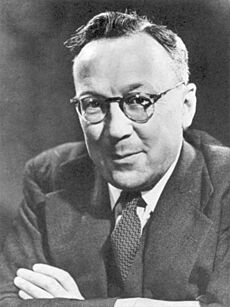
In 1915, Robert Watson-Watt joined the Met Office to study weather. He used radio signals from lightning to map thunderstorms. By 1923, he used oscilloscopes to show these signals. His work eventually led to the Radio Research Station (RRS) in 1927.
As war seemed likely, Britain focused on using science for defense. In 1934, the Air Ministry formed the "Tizard Committee" to see how new science could help defend against air attacks.
H. E. Wimperis, from the Air Ministry, heard about a German "death ray" using radio signals. He asked Watson Watt if such a thing was possible. Watson Watt and his assistant, Arnold F. 'Skip' Wilkins, quickly figured out it would need huge amounts of energy and was unlikely. But Watson Watt added a key idea: "Attention is being turned to the still difficult, but less unpromising, problem of radio detection and numerical considerations on the method of detection by reflected radio waves will be submitted when required."
Wilkins then worked on the radio detection problem. He calculated the power needed, how aircraft would reflect signals, and receiver sensitivity. He suggested using a directional receiver and timing the signals on an oscilloscope to measure distance. Watson Watt sent this idea to the Air Ministry in a secret report on February 12, 1935.
The Air Ministry wanted proof that radio signals would reflect off aircraft. On February 26, 1935, Wilkins set up equipment. A bomber flew between his receiver and a BBC radio station. The aircraft reflected the BBC signal, and Wilkins easily detected it up to 8 miles (13 km) away. This test, called the Daventry Experiment, convinced the Air Ministry to build a full system.
A preliminary system was built at the RRS. Edward George Bowen joined the team to build a powerful transmitter. His transmitter worked at 6 MHz (50 meters wavelength) and sent out 25-microsecond pulses.
The test site was Orfordness, a peninsula in Suffolk. In mid-May 1935, the equipment was moved there. On June 17, the first target was detected: a flying boat 17 miles (27 km) away. This was the first time radio-based detection and ranging was shown in Britain. Watson Watt, Wilkins, and Bowen are given credit for starting radar in Britain.
In December 1935, the British government approved £60,000 for a five-station system called Chain Home (CH). It would cover the approaches to the Thames Estuary. The term RDF (Range and Direction Finding) was used as a secret code name.
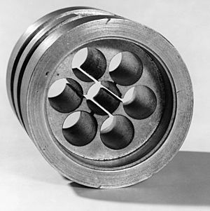
In 1940, John Randall and Harry Boot invented the cavity magnetron. This small device, about the size of a dinner plate, made 10-centimeter wavelength radar possible. It could be carried on aircraft, and its short wavelength meant small antennas. This made it very good at finding submarines from the air.
Air Ministry
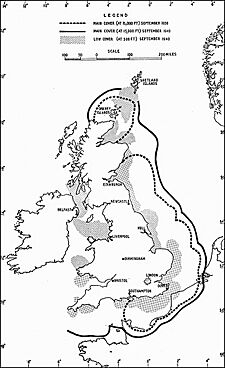
In March 1936, the radar work moved to Bawdsey Manor. The Chain Home (CH) equipment was set up as a prototype. After some initial problems, the system worked well, and the Air Ministry planned a larger network of stations.
The CH stations used transmitters that could switch between four frequencies (20 to 55 MHz) and had a peak power of 200 kilowatts. They sent out pulses lasting 5 to 25 microseconds. Tall steel towers held the transmitting antennas, and wooden towers held the receiving antennas.
By summer 1937, 20 CH stations were being tested. A major exercise by the Royal Air Force (RAF) was a big success. This led to £10,000,000 being approved for a full chain of coastal stations. By early 1938, the RAF took over all CH stations, and the network began regular operations.
E. G. Bowen's team also worked on airborne radar equipment, focusing on 200 MHz (1.5 m) sets. Higher frequencies allowed smaller antennas, which were good for aircraft.
British Army
In 1931, W. A. S. Butement and P. E. Pollard at the Army's Signals Experimental Establishment (SEE) looked at using pulsed 600 MHz signals to detect ships. But the War Office didn't pursue it.
As the Air Ministry's radar work progressed, the Army set up an "Army Cell" at Bawdsey in October 1936. This group focused on two types of radar: gun-laying (GL) systems for anti-aircraft guns and coastal-defense (CD) systems.
Pollard led the first project, a truck-mounted gun-laying radar called Mobile Radio Unit (MRU). It operated at 23 MHz (13 m) with 300 kilowatts of power. It could detect aircraft 60 miles (96 km) away. The Air Ministry also used this system as a mobile backup for the CH system.
In early 1938, Butement started developing a CD system based on Bowen's airborne sets. He designed a large antenna array that could rotate, giving narrower beams and better accuracy. He also created the first "radar range equation" in Britain, which calculates how far a radar can see.
By May 1939, the CD radar could detect aircraft flying as low as 500 feet (150 m) and up to 25 miles (40 km) away. It could also find a 2,000-ton ship 24 miles (39 km) away with great accuracy.
The Royal Navy started its own radar development in September 1935 at His Majesty's Signal School (HMSS) in Portsmouth. They worked on frequencies between 75 MHz and 1.2 GHz.
In August 1937, John D. S. Rawlinson improved their Type 79X radar. He lowered the frequency to 43 MHz (7 meters wavelength). This Type 79Y system had separate transmitting and receiving antennas.
Prototypes of the Type 79Y air-warning system were successfully tested at sea in early 1938. They could detect aircraft 30 to 50 miles (48 to 80 km) away. These systems were then put on the cruiser HMS Sheffield and the battleship HMS Rodney. These were the first Royal Navy ships with radar.
United States' Radar Story
In the United States, both the Navy and Army needed ways to find enemy ships and aircraft. They started developing radio equipment in 1930, mostly separately.
In 1922, Albert H. Taylor and Leo C. Young at the U.S. Naval Aircraft Radio Laboratory noticed a wooden ship interfering with their radio signals. They thought this could be used to detect ships, but the idea wasn't used then. In 1930, Lawrence A. Hyland detected a passing aircraft using a similar setup. This led to a patent for detecting ships and aircraft.
A simple system could detect an object, but not its exact location or speed. That needed pulsed radar. Young suggested pulsing techniques. Robert Morris Page was tasked with this. He designed a transmitter that sent out 60 MHz pulses, 10 microseconds long. In December 1934, this system detected a plane one mile (1.6 km) away. This showed the basic idea of pulsed radar. Page, Taylor, and Young are usually credited with building the world's first pulsed radar.
Page also invented the duplexer. This device allowed the transmitter and receiver to use the same antenna without damaging the sensitive receiver. This was important for accurate long-range detection.
Experiments continued, focusing on improving the receiver. In June 1936, the Navy's first prototype radar, operating at 28.6 MHz, tracked an aircraft up to 25 miles (40 km) away. Because it used low frequencies, it needed very large antennas, making it hard to put on ships or planes.
The frequency was increased to 200 MHz, allowing much smaller antennas. This new system was tested in April 1937. That same month, it was tested on the USS Leary at sea.
Based on these successes, the Navy improved the system. Page developed the ring oscillator, increasing power to 15 kilowatts. They used a large "bedspring" antenna. In 1938, this system, called XAF, detected planes up to 100 miles (160 km) away. It was installed on the battleship USS New York in January 1939, becoming the first operational radar in the U.S. fleet.
In May 1939, RCA was hired to produce it. Called CXAM, deliveries started in May 1940. The acronym RADAR was created from "Radio Detection And Ranging." One of the first CXAM systems was on the USS California, which was sunk during the Japanese attack on Pearl Harbor on December 7, 1941.
United States Army
In 1930, the U.S. Army Signal Corps moved its labs to Fort Monmouth, New Jersey. William R. Blair became the director. He was in charge of research on detecting aircraft using sound and infrared light.
In 1934, the Army Signal Corps started looking into radio-echo techniques. They called it radio position-finding (RPF). They first tried microwaves. In 1934 and 1935, tests showed Doppler-shifted signals from a few hundred feet to over a mile.
Blair wasn't aware of the Navy's success with pulsed radar in 1934. But in 1935, he thought about sending out interrupted radio waves and detecting echoes in between.
In 1936, W. Delmar Hershberger started a small project on pulsed microwave transmission. After visiting the Navy lab, he and Robert H. Noyes built an experimental system using a 75-watt, 110 MHz transmitter with pulse modulation. The War Department initially refused funding, but $75,000 was taken from another project.
In October 1936, Paul E. Watson led the project. On December 14, 1936, their experimental system detected aircraft flying near New York City up to 7 miles (11 km) away.
Work then began on a prototype. They used separate receivers and antennas for direction (azimuth) and height (elevation). The system was meant to aim a searchlight. On May 26, 1937, they showed it to the Secretary of War. A bomber was detected and lit up by the searchlight. The Secretary was so impressed that he ordered full development, and Congress gave $250,000.
The frequency was increased to 200 MHz. The transmitter used 16 tubes, producing about 75 kilowatts of peak power. Engineers from Western Electric and Westinghouse helped. This system, called SCR-268, was successfully shown in late 1938. Production started in 1939, and it entered service in early 1941.
Even before the SCR-268 was in service, it was improved. Harold A. Zahl led a project that created the SCR-270 (mobile) and SCR-271 (fixed-site) versions. These operated at 106 MHz and had a single water-cooled tube providing 8 kilowatts (100 kilowatts pulsed) of power. Westinghouse started deliveries in late 1940.
The Army put five SCR-270 sets around Oahu, Hawaii. At 7:02 AM on December 7, 1941, one of these radars detected a flight of aircraft 136 miles (219 km) to the north. The warning was mistaken for U.S. bombers. The alarm was ignored, and at 7:48 AM, Japanese aircraft attacked Pearl Harbor.
USSR's Radar Beginnings
In 1895, Alexander Stepanovich Popov developed a device to detect distant lightning. In 1897, while testing radio communication between ships, he noticed interference from a third vessel. He wrote that this could be used to detect objects, but didn't do more with it.
After the 1917 Russian Revolution and the creation of the Union of Soviet Socialist Republics (USSR) in 1924, German aircraft could fly deep into Soviet territory. So, finding aircraft at night or above clouds became very important for the Soviet Air Defense Forces (PVO).
Pavel K. Oshchepkov, a physicist, was researching optical devices for the PVO. In June 1933, he switched to radio techniques and started developing a "reconnaissance electromagnetic station." He became responsible for "radio-location" techniques and headed a Special Design Bureau (SKB) in Leningrad.
Early Radio-Location Systems
The Main Artillery Administration (GAU) of the Red Army also worked on aircraft detection. M. M. Lobanov was in charge. He turned to the Central Radio Laboratory (TsRL) in Leningrad. There, Yu. K. Korovin was researching VHF communications. On January 3, 1934, he detected a Doppler signal from an aircraft at 600 meters (0.37 miles) range.
A major conference on detection methods was held in Leningrad in January 1934. Abram Fedorovich Ioffe, a top Russian physicist, chaired it. Radio-location got the most attention. The findings were published, sharing all known information on radio-location in the USSR.
The GAU also made an agreement with the Leningrad Electro-Physics Institute (LEPI) for a radio-location system. B. K. Shembel led this. LEPI built an experimental bi-static (separate transmitter and receiver) system called Bistro (Rapid).
The Bistro transmitter operated at 4.7 meters (64 MHz) and produced about 200 watts. It created a wide "radio screen." A receiver, located some distance away, detected the Doppler-interference when an aircraft entered the screen.
Bistro was first tested in summer 1934. With the receiver 11 kilometers (6.8 miles) from the transmitter, it detected aircraft at about 3 kilometers (1.9 miles). It couldn't directly measure range.
LEPI and TsRL became part of a new GAU organization, Scientific Research Institute #9 (NII-9), in 1935. Mikhail A. Bonch-Bruevich, a famous radio physicist, became its Scientific Director.
Research on magnetrons began at Kharkov University in Ukraine in the mid-1920s. Abram A. Slutskin led the Laboratory of Electromagnetic Oscillations (LEMO), which developed advanced magnetrons.
In 1936, one of these magnetrons, producing 7 watts at 18 cm (1.7 GHz), was used in a "radio-seeker" called Burya (Storm). It detected objects about 10 kilometers (6.2 miles) away and estimated direction within 4 degrees. It wasn't a pulsed system, so it couldn't provide range.
While Shembel and Bonch-Bruyevich worked on continuous-wave systems, Oshehepkov and V. V. Tsimbalin worked on a pulsed system. In 1936, they built a radio-location set operating at 4 meters (75 MHz) with 500 watts peak power. Tests showed aircraft detected at 7 kilometers (4.3 miles). In April 1937, with more power, it detected aircraft near 17 kilometers (11 miles). Even though it was pulsed, it couldn't directly determine range yet.
Pre-war Radio Location Systems
In June 1937, all radio-location work in Leningrad suddenly stopped. Joseph Stalin's Great Purge affected military leaders and scientists. Oshchepkov was sent to a labor camp. NII-9 was saved, but Shembel was dismissed, and Bonch-Bruyevich became director.
The Scientific Research Institute of Signals of the Red Army (NIIIS-KA), which had initially opposed radio-location, gained power and pushed for fast development. They took over Oshchepkov's lab.
At Oshchepkov's former lab, A. I. Shestako continued work on the 4-meter (75 MHz) pulsed system. In July 1938, a fixed system detected aircraft at 30 kilometers (19 miles) at low altitude, and 95 kilometers (59 miles) for high-flying targets. It still couldn't directly determine range. This project led to a mobile system called Redut (Redoubt). It used new transmitter tubes, giving 50 kilowatts peak power, and Yagi antennas.
The Redut was first tested in October 1939 near Sevastopol. It detected a flying boat up to 150 kilometers (93 miles) away. An improved version, Redut-K, was developed by Aksel Berg in 1940 and put on the cruiser Molotov in April 1941. This was the first Soviet warship with radar.
At NII-9, scientists developed advanced microwave generators. Nikolay Devyatkov developed a klystron tube in 1938, which produced 25 watts at 15–18 cm. D. E. Malyarov and N. F. Alekseyev built magnetrons, with the best producing 300 watts at 9 cm.
D. S. Stogov improved the Bistro system, renaming it Reven (Rhubarb). It was tested in August 1938. With minor improvements, it became a mobile system called Radio Ulavlivatel Samoletov (RUS, Radio Catcher of Aircraft), or RUS-1. This continuous-wave system had a truck-mounted transmitter and two truck-mounted receivers.
The RUS-1 system was tested and produced in 1939, entering service in 1940. About 45 RUS-1 systems were built. However, without direct range measurement, the military found it not very useful.
The NIIIS-KA also hired the UIPT in Kharkov to develop a pulsed radio-location system for anti-aircraft use. This led to the Zenit project in March 1937. Aleksandr S. Usikov developed a 60 cm (500 MHz) magnetron that produced 3 kilowatts pulsed power, later increased to 10 kilowatts. Semion Braude developed a receiver. The system had separate transmitting and receiving antennas with parabolic reflectors.
Zenit was first tested in October 1938, detecting a bomber at 3 kilometers (1.9 miles). In September 1940, an improved Zenit could determine the range, altitude, and direction of an aircraft up to 25 kilometers (16 miles) away. But it took 38 seconds for measurements, too long for anti-aircraft guns.
Work continued on Zenit to make it a single-antenna system called Rubin. But this was stopped by the German invasion in June 1941.
After eight years of work, the USSR entered World War II without a fully developed and deployed radar system.
Japan's Radar Story
Japan, as a seafaring nation, was interested in wireless (radio) communications early on. The Imperial Japanese Navy used wireless telegraphy in 1904. They also developed good radio direction-finding receivers by 1921.
Between the World Wars, Japan's radio technology advanced well. However, military leaders often didn't see the need for new technologies. They believed their existing weapons were enough. In 1936, Japan joined Nazi Germany and Fascist Italy.
Technology Background
Radio engineering was strong in Japanese universities. They researched basic technologies like high-frequency and high-power oscillators, including the cavity magnetron.
Professor Hidetsugu Yagi was a well-known radio researcher. In 1928, he published a paper summarizing radio research at Tohoku University. With Shintaro Uda, one of his students, he developed a new antenna called the Yagi antenna. This antenna is still widely used today.
The cavity magnetron also interested Yagi. In 1927, Kinjiro Okabe, another student, developed a magnetron that could generate waves as short as 12 cm (2.5 GHz).
Other Japanese researchers also improved magnetrons. Shigeru Nakajima at Japan Radio Company (JRC) saw a commercial use for magnetrons in medical heating. The only military interest came from Yoji Ito at the Naval Technical Research Institute (NTRI).
In 1936, Tsuneo Ito developed an 8-split-anode magnetron that produced 10 watts at 10 cm (3 GHz). It was called Tachibana (Mandarin orange). In 1937, Tsuneo Ito and Yoji Ito developed a way to make magnetrons more stable, which was a big breakthrough.
By early 1939, NTRI/JRC had a 10-cm (3-GHz) stable magnetron that could produce 500 watts. They also built magnetrons for even shorter wavelengths. Their M3 magnetron was similar to the one developed by Boot and Randall in Britain in 1940.
Japan had strong scientific and engineering skills. They were ahead of Britain in magnetron development, and their Yagi antenna was a world standard. But their military leaders didn't see the value of radio detection and ranging (RRF), especially for defense. They focused on offense.
Imperial Army
In 1938, engineers at Nippon Electric Company (NEC) noticed rapid fading of high-frequency signals when an aircraft flew overhead. Masatsugu Kobayashi, NEC's Tube Department Manager, realized this was due to the Doppler effect from the reflected signal.
Kobayashi suggested to the Army that this could be used for aircraft warning. The Army had rejected earlier radio-detection ideas, but this one was simple and cheap to test. NEC assigned Kinji Satake to develop a system called the Bi-static Doppler Interference Detector (BDID).
For testing, the prototype was set up along the coast of China. It operated between 4.0–7.5 MHz and used widely spaced stations. This created a "radio screen" that could detect an aircraft's presence (but nothing else) up to 500 kilometers (310 miles) away. The BDID was the Imperial Army's first deployed radio detection system, in early 1941.
A similar system was developed for Japan itself. Information centers received warnings from BDID stations, usually 65 to 240 kilometers (40 to 150 miles) apart. To prevent enemies from finding the transmitters, they used only a few watts of power. These systems stayed in use throughout the war. The Imperial Army didn't have true radar until after the war started.
In the mid-1930s, some Imperial Navy specialists became interested in using radio to detect aircraft. They asked Professor Yagi, who suggested looking at the Doppler frequency-shift in reflected signals.
Funding was given to Osaka Laboratory for experiments. Kinjiro Okabe led the effort. In 1936, Okabe successfully detected a passing aircraft using the Doppler-interference method. This was the first time aircraft detection by radio was recorded in Japan. However, this didn't lead to much funding. Top naval officials thought the risks of enemy detection outweighed the benefits.
Historically, warships used lights and horns to avoid collisions in fog. Yoji Ito at the NTRI suggested using a very narrow beam from a magnetron to reduce the chance of enemy detection.
Development of a microwave system for collision avoidance started in 1939. Yoji Ito and Shigeru Nakajima designed a system using a 3-cm (10-GHz) magnetron. Initial tests were poor due to low power.
They replaced it with a 16-cm (1.9-GHz) magnetron with higher power. In October 1940, it got clear echoes from a ship in Tokyo Bay about 10 kilometers (6.2 miles) away. Still, top Japanese naval officials didn't fully commit to using this technology.
In late 1940, Japan sent two technical missions to Germany to exchange military technology information. Commander Yoji Ito represented the Navy. They exchanged general information, but little about radio-detection. Neither side mentioned magnetrons. The Germans did mention using pulsed techniques.
After these reports, the Naval General Staff changed its mind and accepted pulse-transmission technology. On August 2, 1941, funds were given for developing pulse-modulated radars.
A prototype system operating at 4.2 meters (71 MHz) and producing 5 kilowatts was quickly built. Kenjiro Takayanagi, called "the father of Japanese television," helped develop the pulse and timing circuits. In early September 1941, the prototype detected a single bomber at 97 kilometers (60 miles) and a group of aircraft at 145 kilometers (90 miles).
This system, Japan's first full Radio Range Finder (RRF – radar), was called Mark 1 Model 1. Production contracts were given to three companies. It operated at 3.0 meters (100 MHz) with 40 kilowatts peak power.
In November 1941, the first RRF was put into service as a land-based early-warning system at Katsuura, Chiba. It weighed almost 8,700 kg (19,000 lb). It could detect single aircraft at 130 kilometers (81 miles) and groups at 250 kilometers (160 miles).
Netherlands' Radar Work
Early radio detection in the Netherlands happened in two separate ways: a microwave system at Philips and a VHF system at an Armed Forces lab.
The Philips Company had a research lab (NatLab). Researcher Klaas Posthumus developed a magnetron. While testing a communication system with it, they noticed a large plate reflected a strong signal.
Recognizing this could be a detection device, NatLab showed it to the Royal Netherlands Navy in 1937. Even though sea waves interfered, the Navy was impressed and sponsored more research. In 1939, an improved system detected a vessel 3.2 kilometers (2 miles) away.
Philips built a prototype, and plans were made for a chain of warning stations. But the project stopped when Germany invaded the Netherlands on May 10, 1940. However, the work continued secretly within NatLab until 1942.
In the early 1930s, rumors of a "death ray" led the Dutch Parliament to set up a committee. The committee dismissed death rays but established the Laboratory for Physical Development (LFO) to support the Armed Forces.
In 1934, J.L.W.C. von Weiler and S.G. Gratama at LFO started researching a 1.25-meter (240 MHz) communication system for artillery spotting.
In 1937, during tests, a flock of birds disturbed the signal. Realizing this could detect aircraft, the Minister of War ordered more experiments. Weiler and Gratama developed a system to direct searchlights and aim anti-aircraft guns.
Their experimental "electrical listening device" operated at 70 cm (430 MHz) and used pulsed transmission. It detected an aircraft 18 kilometers (11 miles) away in April 1938. However, the Army rejected it because it couldn't handle harsh combat conditions.
The Navy was more open to it. Funding was provided, and Max Staal joined the team. To keep it secret, they built parts at different universities. Ten sets were to be assembled.
The prototype had a peak power of 1 kilowatt. Several sets were completed, and one was put into operation in The Hague just before the Netherlands fell to Germany in May 1940. It worked well, spotting enemy aircraft. To prevent capture, the systems and plans were destroyed. Von Weiler and Max Staal escaped to England with two disassembled sets.
France's Radar Efforts
In 1927, French physicists Camille Gutton and Emile Pierret experimented with magnetrons that produced very short wavelengths. Camille's son, Henri Gutton, improved these magnetrons.
In 1934, Maurice Ponte's research team filed a patent for a device to detect obstacles using continuous waves from a magnetron. This was a CW (continuous wave) system that used the Doppler effect. It could measure distance and direction. This was the first patent for an operational radio-detection device using centimeter wavelengths.
The system was tested in late 1934 on the cargo ship Oregon. It detected coastlines and boats from 10–12 nautical miles (19–22 km) away. The shortest wavelength was chosen for the final design, which was put on the liner SS Normandie in mid-1935.
In late 1937, Maurice Elie developed a way to pulse-modulate transmitter tubes. This led to a new 16-cm system with 500 watts peak power. It was planned for sea-testing on the Normandie, but this was canceled when war broke out.
At the same time, Pierre David experimented with reflected radio signals at about a meter wavelength. Starting in 1931, he noticed aircraft caused interference. His lab began researching an "electromagnetic curtain" detection technique. It could show general location but not precise direction or speed.
In 1936, David's electromagnetic curtain was tested. It detected most aircraft but missed too many. As war neared, the need for aircraft detection became critical. David realized the benefits of a pulsed system. In October 1938, he designed a 50 MHz, pulse-modulated system with 12 kilowatts peak power.
France declared war on Germany on September 3, 1939. The SADIR system was taken near Toulon and detected invading aircraft up to 55 kilometers (34 miles) away. The SFR pulsed system near Paris detected aircraft up to 130 kilometers (81 miles). But the German advance was too fast. France decided to share its breakthroughs with its allies.
In mid-1940, Maurice Ponte gave a cavity magnetron designed by Henri Gutton to the GEC laboratories in Britain. This magnetron was for pulsed operation at 16 cm. It used an oxide-coated cathode, which was important for producing high-power pulses at short wavelengths. This was a significant contribution to British radar. A tweaked version reached 10 kilowatts by August 1940. This model was given to the Americans by the Tizard Mission in 1940.
Italy's Radar Efforts
Guglielmo Marconi started radar research in Italy. In 1933, he noticed disturbances in a 600 MHz communication link across Rome caused by moving objects. This led to his "radioecometro," a 330 MHz (0.91-m) CW Doppler detection system.
In May 1935, Marconi showed his system to Benito Mussolini, Italy's leader. The power was too low for military use. While it sparked interest, little more was done with his device.
Mussolini ordered further development, assigning it to the Royal Institute for Electro-technics and Communications (RIEC). Lieutenant Ugo Tiberio, a physics instructor, was assigned to lead the project part-time.
Tiberio wrote a report in mid-1936 on developing an experimental device called "Radio-Detector Telemetry" (RDT). The report included what became known as the radar range equation. Nello Carrara, a physics instructor, was added to develop the RDT transmitter.
By the end of 1936, Tiberio and Carrara demonstrated the EC-1, the first Italian RDT system. It used an FM transmitter at 200 MHz and detected objects by mixing signals, creating an audible tone.
The EC-1 didn't measure range. To add this, they started developing a pulsed system in 1937. Captain Alfeo Brandimarte designed the EC-2. It operated at 175 MHz and used a single antenna. But it had many problems and was never tested.
Work then focused on higher power and frequencies. Carrara developed a magnetron-like device that produced 10 kilowatts at 425 MHz (70 cm). This was used to design two versions of the EC-3, one for ships and one for coastal defense.
Italy entered WWII in June 1940 without an operational RDT. A test version of the EC-3 was built, but most RDT work stopped to support the war directly.
Other Countries' Radar Work
In early 1939, Britain invited representatives from its most advanced Commonwealth Nations to learn about secret RDF (radar) technology. Based on this, radar developments started in Australia, Canada, New Zealand, and South Africa by September 1939. Hungary also developed its own radar during the war.
Australia: The Radiophysics Laboratory in Australia started developing radar. Their first project was a 200 MHz (1.5-m) shore-defense system for the Australian Army. Called ShD, it was first tested in September 1941 and installed at 17 ports. After the Japanese attack on Pearl Harbor, the Royal Australian Air Force needed an air-warning system. Piddington's team quickly built the AW Mark I in five days. It was being installed in Darwin, Northern Territory, when Australia was first attacked by Japan in February 1942. Later, a lighter, portable version, the LW-AW Mark II, was used by Australian and U.S. forces in the South Pacific.
Canada: Early radar developments in Canada were at the Radio Section of the National Research Council of Canada. John Tasker Henderson led a team that developed the Night Watchman, a surface-warning system for the Royal Canadian Navy to protect Halifax Harbour. Tested successfully in July 1940, it operated at 200 MHz (1.5 m) with 1 kilowatt output. This was followed by a ship-borne system called Surface Warning 1st Canadian (SW1C). However, its performance was poor compared to British radar, so the Royal Canadian Navy adopted the British Model 271 instead. For coastal defense, the Canadian Army developed a 200 MHz system called CD, which used a large, rotating antenna. It became operational in January 1942.
New Zealand: Ernest Marsden represented New Zealand in England and set up two radar development facilities. Charles N. Watson-Munro led land-based and airborne sets, while Frederick W. G. White led shipboard sets. By late 1939, they had a 180 MHz (1.6-m), 1 kilowatt transmitter that could detect large vessels up to 30 kilometers (19 miles) away. This was called CW (Coastal Watching). A similar system, CD (Coast Defense), was deployed in Wellington in late 1940. An airborne ASV 200 MHz set from Britain was built into an aircraft set for the Royal New Zealand Air Force and first flown in early 1940. At Christchurch, they tested a 430 MHz (70-cm), 5 kilowatt set by July 1940. Two types, SW (Ship Warning) and SWG (Ship Warning, Gunnery), were put into service by the Royal New Zealand Navy starting in August 1941. New Zealand developed about 44 types of radar during WWII. Transportable GCI radar sets were deployed in the Pacific, including one at Henderson Field, Guadalcanal, in September 1942, where American radars couldn't plot heights well.
South Africa: Basil F. J. Schonland received briefings from Ernest Marsden in 1939. Schonland, an expert on lightning, immediately started radar development using amateur radio parts. His system, JB (for Johannesburg), was a 90 MHz (3.3-m), 500-watt mobile system. It was tested in November 1939, just two months after starting. The prototype operated in Durban and detected ships and aircraft up to 80 kilometers (50 miles) away. By March 1940, a system was fielded by anti-aircraft brigades.
Hungary: Zoltán Lajos Bay, a physics professor and research director, was asked to develop a radar system in late 1942. Using information on pulsed transmission, Bay developed a system called Sas (Eagle) from existing communication hardware. The Sas operated at 120 MHz (2.5 m) and was on a rotating platform. Records say it had a range of "better than 500 km" when tested in 1944. There's no sign it was in regular service. After the war, Bay used a modified Sas to successfully bounce a signal off the moon.
World War II Radar
When World War II started in September 1939, both the UK and Germany knew about each other's work in radio navigation and countermeasures. They were also very interested in each other's radar developments and used spying and false information. By the Battle of Britain, both sides used radar and control stations as part of their air defense. However, German radar systems couldn't help with offensive attacks, so Adolf Hitler didn't support them much. Also, the Luftwaffe didn't fully understand how important British radar stations were to the RAF's air defense, which contributed to their failure.
While the UK and Germany led in pre-war radar advances, the United States, the Soviet Union, and Japan also developed systems. The acronym RADAR (for RAdio Detection And Ranging) was created by the U.S. Navy in 1940 and quickly became widely used. The XAF and CXAM search radars were the first operational radars in the U.S. fleet.
When France fell to the Nazis, Britain didn't have money to mass-produce the cavity magnetron. So, Churchill agreed that Sir Henry Tizard should offer the magnetron to the Americans in exchange for their financial and industrial help (the Tizard Mission). An early 6 kW version, built in England, was given to the US government in September 1940. The British magnetron was a thousand times more powerful than the best American transmitter at the time and produced accurate pulses. The cavity magnetron was widely used in World War II microwave radar equipment. It is often credited with giving Allied radar a big advantage over German and Japanese radars, directly helping the Allies win the war. Historian James Phinney Baxter III called it "The most valuable cargo ever brought to our shores."
The Bell Telephone Laboratories made a version of the magnetron that could be produced easily. By the end of 1940, the Radiation Laboratory was set up at Massachusetts Institute of Technology to develop radars using the magnetron. By early 1941, portable airborne radars were being tested in American and British aircraft. In late 1941, the Telecommunications Research Establishment in Britain used the magnetron to develop a revolutionary airborne, ground-mapping radar called H2S. Magnetron radars used by the US (like H2X) and Britain could even spot a U-boat's periscope.
Post-War Radar
World War II ended in May 1945 (Europe) and August 1945 (Japan). Radar activities in Germany and Japan stopped for years. In other countries, especially the United States, Britain, and the USSR, radar continued to improve for military uses during the Cold War. These countries even brought German scientists and engineers to work on their weapon programs.
Even before the war ended, projects for non-military radar uses began. The US Army Air Forces and the British RAF had improved radar for aircraft landing, which quickly expanded to civilian airports. Radio astronomy also grew rapidly after the war, with many scientists using their radar experience.
Four important radar techniques became common in the late 1940s and early 1950s: pulse Doppler, monopulse, phased array, and synthetic aperture. Some were known during the war but were perfected later.
- Pulse-Doppler radar (also called moving target indication or MTI) uses the Doppler-shifted signals to better find moving targets even with background "clutter."
- Monopulse radar (also called simultaneous lobing) was invented by Robert Morris Page in 1943. It gets angle information from a single pulse, making tracking much more accurate.
- Phased-array radar has many parts of a large antenna controlled separately. This allows the radar beam to be directed very quickly. It can track multiple targets almost at the same time while watching a large area.
- Synthetic-aperture radar (SAR) was invented in the early 1950s. It uses a single, small antenna on an aircraft. It combines signals from each pulse to create a high-resolution image of the ground, like a much larger antenna would. SAR is used for mapping and remote sensing.
Early uses of digital computers in radar were for switching the signal phase in phased-array antennas. As computers got smaller, they were used for digital signal processing to improve radar performance.
Many other radar advances and uses happened after WWII. The following sections give some examples.
Military Radars
In the United States, the Rad Lab at MIT closed in 1945. The Naval Research Laboratory (NRL) and the Army's Evans Signal Laboratory continued developing centimeter radar. The United States Air Force (USAF) focused radar research at their Cambridge Research Center. In 1951, MIT opened the Lincoln Laboratory for joint projects.
In Britain, the RAF's Telecommunications Research Establishment (TRE) and the Army's Radar Research and Development Establishment (RRDE) continued at a smaller scale. In 1953, they combined to form the Radar Research Establishment. In 1948, all Royal Navy radio and radar R&D combined to form the Admiralty Signal and Radar Establishment. The USSR, despite war damage, immediately started developing new weapons, including radars.
During the Cold War, the main conflict was between the United States and the Soviet Union. By 1949, both had nuclear weapons carried by bombers. To give early warning of an attack, both built huge, complex radar networks in remote places. In the West, the first was the Pinetree Line across Canada in the early 1950s.
Soviet technology improved, making these lines not good enough. So, the Distant Early Warning Line (DEW Line) was completed in 1957. It stretched over 6,000 miles (9,700 km) from Alaska to Baffin Island. It had 63 stations with powerful radars. When the Soviet Union tested its first Intercontinental Ballistic Missile (ICBM) in 1957, the DEW Line became even more important.
Both the U.S. and the Soviet Union then developed anti-ballistic missile (ABM) systems. The USSR had the Fakel V-1000, with powerful radars. The U.S. Army started the Nike-X ABM system, which became the Safeguard Program. It had a long-range Perimeter Acquisition Radar (PAR) and a shorter-range Missile Site Radar (MSR).
The PAR was in a 128-foot (39 m) tall building. It had 6,888 antenna elements for transmitting and receiving. It could detect incoming missiles outside the atmosphere up to 1,800 miles (2,900 km) away. The MSR had an 80-foot (24 m) pyramid shape with four phased-array antennas. It could search for targets in all directions, finding them up to 300 miles (480 km) away.
One Safeguard site was completed in October 1975, but the U.S. Congress stopped funding after only one day. Over the next decades, the U.S. Army and Air Force developed many large radar systems.
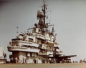
A modern radar developed by the U.S. Navy is the AN/SPY-1. First used in 1973, this 6 MW system is a key part of the Aegis Combat System. It's computer-controlled and uses four antennas to cover a hemisphere.
Radar signals usually travel in a straight line, so their range to ground targets is limited by the visible horizon, about 10 miles (16 km). Airborne targets can be seen further, but usually only a few hundred miles. Since the beginning of radio, it was known that certain frequencies (3 to 30 MHz) could "bounce" off the ionosphere and be received far away. As long-range bombers and missiles appeared, there was a need for radars that could give early warnings at great distances. In the early 1950s, the Naval Research Laboratory developed Over-the-Horizon (OTH) radar for this.
To tell targets apart from other reflections, they used a phase-Doppler system. They needed very sensitive receivers and powerful transmitters with large antennas. Computers were needed to analyze the data. In 1950, their first experimental system detected rocket launches 600 miles (970 km) away and a nuclear explosion cloud 1,700 miles (2,700 km) away.
In the early 1970s, a joint American-British project, Cobra Mist, used a 10 MW OTH radar in England to detect aircraft and missile launches over the Western USSR. It was abandoned due to US-USSR ABM agreements. At the same time, the Soviets developed a similar system, Duga (Arc), known as the Russian Woodpecker by radio amateurs because of its interference. Australia, Canada, and France also developed OTH radar systems.
With the arrival of satellites for early warning, the military lost interest in OTH radars. However, recently, this technology has been used again to detect and track ships for things like maritime reconnaissance and drug enforcement.
Civil Aviation Radars
After the war, radar brought a big change to Air Traffic Control (ATC). In 1946, the Civil Aeronautics Administration (CAA) showed an experimental radar-equipped tower for controlling civilian flights. By 1952, the CAA started using radar for approach and departure control. Four years later, they ordered many long-range radars for "en route" ATC, which could see aircraft up to 200 nautical miles (370 km) away at higher altitudes. In 1960, aircraft in certain areas had to carry a radar transponder that identified the aircraft and improved radar performance. Since 1966, the agency has been called the Federal Aviation Administration (FAA).
A Terminal Radar Approach Control (TRACON) is an ATC facility near a large airport. It controls aircraft within a 30 to 50 nautical mile (56 to 93 km) radius of the airport, between 10,000 and 15,000 feet (3,000 to 4,600 m) altitude. It uses one or more Airport Surveillance Radars (ASR-8, 9, and 11), which scan the sky every few seconds. These primary radars are usually paired with secondary radars (Air Traffic Radar Beacon Interrogators, or ATCBI). Unlike primary radar, secondary radar relies on an aircraft's transponder, which replies with a digital code including the aircraft ID and altitude. This is similar to military IFF (Identification friend or foe). The secondary radar antenna sits on top of the primary radar dish, and both rotate about 12 times per minute.
The Digital Airport Surveillance Radar (DASR) is a newer TRACON system that replaces old analog systems with digital technology. The civilian names are ASR-9 and ASR-11.
The ASR-11 includes two radar systems. The primary is an S-Band (~2.8 GHz) system with 25 kilowatts pulse power. It tracks aircraft in 3D and measures rainfall intensity. The secondary is a P-Band (~1.05 GHz) system with about 25 kilowatts peak power. It uses a transponder to ask aircraft for data. The antennas for both systems rotate on a tall tower.
Weather Radar
During World War II, military radar operators noticed "noise" in echoes from weather elements like rain and snow. After the war, scientists developed ways to use these echoes. In the United States, David Atlas developed the first working weather radars. In Canada, J.S. Marshall and R.H. Douglas formed the "Stormy Weather Group." Marshall and Walter Palmer are known for their work on how rain drop sizes relate to radar signals. In the UK, research continued on radar echo patterns and weather, testing different wavelengths.
Between 1950 and 1980, reflectivity radars, which measure the position and intensity of precipitation, were built worldwide. In the U.S., the U.S. Weather Bureau developed the WSR-1 (Weather Surveillance Radar-1), one of the first weather radars. This was a modified military radar. It was followed by the WSR-57 (Weather Surveillance Radar – 1957), the first weather radar designed for a national warning network. It used old vacuum tube technology and gave only basic data. It operated at 2.89 GHz (S-Band) with 410 kilowatts peak power and a range of about 580 miles (930 km).
Early meteorologists watched a cathode ray tube. In the 1970s, radars became standardized and organized into larger networks. The next big change in the U.S. was the WSR-74 series, starting in 1974. These were transistor-based. Until the 1990s, there were 128 WSR-57 and WSR-74 radars across the country.
The first devices to capture radar images were developed then. More scanned angles gave a 3D view of precipitation, allowing horizontal and vertical cross-sections. This helped study thunderstorms. In May 1973, a tornado hit Union City, Oklahoma. For the first time, a Doppler radar documented its entire life cycle. Researchers found a rotating cloud before the tornado touched down, which helped convince the National Weather Service that Doppler radar was vital for forecasting.
Between 1980 and 2000, Doppler radar networks became common in North America, Europe, Japan, and other developed countries. Doppler radars could track the speed of particles in the air, not just their position and intensity. In the U.S., the NEXRAD (WSR-88D) network of 10 cm wavelength radars started in 1988. Canada built its King City Doppler radar in 1985, leading to a complete Canadian weather radar network by 2004. France and other European countries also switched to Doppler networks. Fast computer advances led to algorithms to detect severe weather.
After 2000, dual polarization technology became operational. This increases information about precipitation type (e.g., rain vs. snow). "Dual polarization" means the radar sends out microwave radiation polarized both horizontally and vertically.
Since 2003, the U.S. National Oceanic and Atmospheric Administration has experimented with phased-array radar to replace traditional antennas. This gives faster updates, which is important for severe thunderstorms.
Also in 2003, the National Science Foundation created "CASA" (Collaborative Adaptive Sensing of the Atmosphere). This group researches and develops small, fast-scanning, dual-polarization radars to improve existing systems by sampling the lower atmosphere.
Mapping Radar
The plan position indicator, an early and common radar display, shows a map of targets around the radar. If an aircraft's radar antenna points down, it creates a map of the ground. Larger antennas give better image resolution. After centimeter radar, downward-looking radars like H2S and H2X provided real-time maps used by the U.S. and Britain for bombing runs over Europe at night or through clouds.
Synthetic-Aperture Radar
In 1951, Carl Wiley led a team that developed synthetic aperture radar (SAR). This technique greatly improved the resolution of radar images. A regular-sized antenna on an aircraft uses complex signal processing to create an image that would normally need a much larger antenna. This is why it's called "synthetic aperture." As each pulse is sent out, it covers an area on the ground. The return signal is spread out in time from reflections at different distances. The aircraft's movement helps create the horizontal details. The signals are combined using math (Fourier transform) to form the image. This is similar to optical holography.
Over the years, many SAR variations have been made for different uses. Early systems were too complex for on-board processing; signals were recorded and processed later. Now, fast electronics allow real-time processing on board. Early systems had resolutions of tens of meters, but newer airborne systems can achieve about 10 cm. Current systems can even get resolutions of a few millimeters.
Other Radars and Uses
There are many other post-war radar systems and uses. Here are a few:
Radar Gun
The most common radar device today is probably the radar gun. This is a small, often hand-held, Doppler radar that measures the speed of objects. It's used by police to check car speeds, and in sports to measure the speed of pitched baseballs or runners. It doesn't give position information, only speed. First developed in 1954, most radar guns use very low power. Some use infrared light or laser light, called LIDAR. A related technology, laser Doppler velocimetry, measures speed in flowing liquids or gases.
Impulse Radar
When pulsed radars were first developed, scientists looked at using very short pulses. A shorter pulse means more accurate distance measurement. Also, for a given pulse rate, a shorter pulse means higher peak power. Shorter pulses also mean a wider range of frequencies. In the early days, the electronics for these pulses weren't available.
By the 1970s, electronics advances renewed interest in short-pulse radar. It became possible to create pulses as short as one cycle of the radio wave. This is now called impulse radar.
The first major use was in ground-penetrating radar (GPR). Developed in the 1970s, GPR is used for analyzing building foundations, archaeological mapping, treasure hunting, and finding unexploded bombs. It can find boundaries between soil and objects. Results depend on the operator's skill and interpretation.
In dry soil, penetration up to 300 feet (91 m) is possible. For short-range measurements, the pulse is often just one radio-frequency cycle long. With a 100 MHz carrier, the pulse lasts only 10 nanoseconds, leading to the "impulse" name. GPR systems are available in backpack and wheeled-cart versions.
With continued electronics development, systems with pulses lasting only picoseconds became possible. Uses include security and motion sensors, building stud-finders, collision-warning devices, and heart monitors. Some of these devices are very small.
Radar Astronomy
As radar developed, astronomers thought about using it to observe the Moon and other nearby objects in space. In 1944, Zoltán Lajos Bay in Hungary aimed to do this. His radar telescope was taken by the Soviet army, delaying his experiment. Under Project Diana in the U.S., a modified SCR-271 radar received echoes from the Moon on January 10, 1946. Zoltán Bay achieved this on February 6.
Radio astronomy also started after WWII. Many scientists from radar development entered this field. Many radio observatories were built, but few were dedicated to radar astronomy because of the extra cost and complexity. Most major radar astronomy activities have been part of radio astronomy observatories.
The radio telescope at the Arecibo Observatory, opened in 1963, was the largest in the world. It was mainly for radio astronomy but had equipment for radar astronomy. It had powerful transmitters. Its 305-meter (1,000-ft) primary reflector was fixed, but the secondary reflector could move to point precisely. Many discoveries were made, including mapping Mars's surface and observing Saturn and its moon, Titan. In 1989, it radar-imaged an asteroid for the first time.
After cable failures in 2020, the telescope was planned for demolition. However, more cables failed, causing the instrument platform to crash through the dish on December 1, 2020. The National Science Foundation plans to keep other facilities operational and look into rebuilding a new telescope.
Several spacecraft orbiting the Moon, Mercury, Venus, Mars, and Saturn have carried radars for surface mapping. A ground-penetration radar was on the Mars Express mission. Radar systems on aircraft and orbiting spacecraft have mapped the entire Earth for various purposes. The Shuttle Radar Topography Mission mapped the entire planet at a 30-meter resolution.
The Jodrell Bank Observatory in Britain, started by Bernard Lovell, was originally a radar astronomy facility. It first used a war-surplus radar system to observe meteor showers in December 1945. While it became the third largest radio observatory, some radar astronomy continued. Its largest telescope tracked Sputnik 1, the first artificial satellite, in October 1957.
See also
- Cavity magnetron
- History of smart antennas
- Klystron
- List of German inventions and discoveries
- List of World War II electronic warfare equipment
- Secrets of Radar Museum
 | Mary Eliza Mahoney |
 | Susie King Taylor |
 | Ida Gray |
 | Eliza Ann Grier |


