
Gear facts for kids

Gears are special mechanical parts with teeth that fit together. They are designed to transfer power and motion from one part to another. You can also call gears "toothed wheels" or "cogs."
What Are Gears Made Of?
Gears are made from many different materials. These include various alloys (mixtures of metals), cast iron, and even plastics. However, steel is the most common material. This is because steel is very strong for its weight and is also cost-effective.
Types of Gears
There are many different types of gears, each designed for specific jobs.
External and Internal Gears

An external gear has its teeth on the outside surface of a cylinder or cone. Think of a regular gear you might see.
An internal gear has its teeth on the inside surface. When an internal gear works with another gear, it does not change the direction of the spinning shaft.
Spur Gears

Spur gears are the simplest type of gear. They look like a flat disk with straight teeth sticking out. The teeth are parallel to the center axis of the gear.
Spur gears work best when they are connected to other gears on parallel shafts (meaning the shafts are side-by-side). They are good for medium speeds. However, they can be a bit noisy when they spin very fast.
Helical Gears


Helical gears are an improved version of spur gears. Their teeth are cut at an angle, not straight. This angled shape makes the teeth look like a part of a spiral.
Helical gears can connect in two ways:
- Parallel: The shafts are parallel to each other. This is the most common way.
- Crossed: The shafts are not parallel. These are sometimes called "skew gears."
Because their teeth engage (or connect) more smoothly, helical gears are quieter and run more smoothly than spur gears. This makes them great for high-speed uses or where noise needs to be kept low.
One small problem with helical gears is that they create a pushing force along the shaft. This force needs special bearings to handle it. They also have a bit more friction between their teeth, which is usually helped by special oils.
Double Helical Gears
.jpg)
Double helical gears solve the pushing force problem of single helical gears. They have two sets of angled teeth that form a "V" shape. It's like having two helical gears mirrored and joined together.
This "V" shape means that the pushing forces from each half cancel each other out. This results in no net pushing force along the shaft, so special bearings might not be needed. However, double helical gears are harder to make because of their complex shape.
Bevel Gears

A bevel gear looks like a cone with its tip cut off. When two bevel gears connect, their imaginary tips must meet at the same point. Their shafts also meet at this point, forming an angle between them. This angle can be anything except straight (0 or 180 degrees).
If two bevel gears have the same number of teeth and their shafts meet at a 90-degree angle, they are called miter gears.
Spiral Bevel Gears

Spiral bevel gears are like bevel gears, but their teeth are curved, similar to how helical gears have angled teeth. This curving makes them run more smoothly and quietly than straight bevel gears.
Straight bevel gears are usually used only for slower speeds.
Hypoid Gears

Hypoid gears look a lot like spiral bevel gears, but there's a key difference: their shafts do not intersect (they don't meet at a point). Instead, one shaft is offset.
Hypoid gears are usually designed to work with shafts at a 90-degree angle. They can be even smoother and quieter than spiral bevel gears. However, they also have a sliding motion between their teeth, so they need very thick gear oil to protect them.
A cool thing about hypoid gears is that they can create very high gear ratios (like 60:1 or more) with just one set of gears. This makes them very common in motor vehicles, especially in the part that connects the engine to the wheels, called the differential.
Crown Gears

Crown gears are a special type of bevel gear. Their teeth stick out at right angles to the flat surface of the wheel, making them look like the points on a crown.
A crown gear usually connects with another bevel gear. Sometimes, they are also seen working with spur gears or in clock mechanisms.
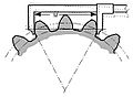
Worm Gears


Worms look like screws. A worm connects with a worm wheel, which looks similar to a spur gear.
Worm-and-gear sets are a simple way to get a very high gear ratio, meaning they can create a lot of turning force (torque) at a very low speed. For example, while helical gears might have ratios less than 10:1, worm gears can go from 10:1 up to 500:1!
One downside is that they can have a lot of sliding motion, which can make them less efficient.
A special feature of some worm-and-gear sets is that they can be self-locking. This means the worm can always turn the gear, but the gear cannot turn the worm. This is useful when you want to set a position and have it stay there, like in the tuning pegs of some musical instruments.
Non-Circular Gears

Non-circular gears are made for special jobs. While most gears aim for smooth, quiet power transfer, non-circular gears are designed to change the speed ratio as they turn.
They are used in things like textile machines, where the speed needs to vary, or in special types of transmissions.
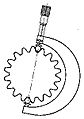
Rack and Pinion

A rack is a straight bar with teeth. You can think of it as a part of a gear that has an extremely large radius.
When a rack connects with a pinion (a small gear), the spinning motion of the pinion is changed into straight-line motion of the rack. This system is used in cars to turn the steering wheel's rotation into the left-and-right movement of the wheels. It's also used in rack railways to help trains climb steep hills.
Epicyclic Gearing

In epicyclic gearing, also known as planetary gearing, one or more of the gear's central axes actually moves.
Sun and Planet Gears

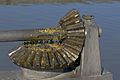
Sun and planet gearing was a clever way to change back-and-forth motion into spinning motion. James Watt used this in his early steam engines. It helped him get around a patent on the crank, and it also made the engine's flywheel spin faster, so he could use a lighter one.
In the picture, the yellow gear is the "sun," and the red gear is the "planet."
Harmonic Gears

A harmonic gear is a very specialized gear system. It's often used in industrial robots and aerospace because it's very compact, has high gear ratios, and has almost no "backlash" (meaning no looseness or play between the teeth).
Cage Gears

A cage gear, also called a lantern gear, has cylindrical rods for teeth. These rods are arranged in a circle, like the bars of a bird cage. Disks at each end hold the rods and the axle in place.
Cage gears are more efficient than solid gears. Dirt can fall through the rods instead of getting stuck and causing wear. They are also easier to make with simple tools. They were often used in clocks, especially large ones like turret clocks, where conditions could be dirty.
Magnetic Gears
Magnetic gears work without touching! Each part of a magnetic gear acts like a magnet, with alternating magnetic poles on its surfaces.
Even though they can't transfer as much force as regular gears, magnetic gears have some great benefits:
- They don't wear out because they don't touch.
- They are very quiet.
- They can slip without being damaged, making them very reliable.
- They can work through a non-metallic barrier, which means they can transfer power into a sealed container without needing a seal that might leak.
Images for kids
-
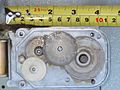
Multiple reducer gears in a microwave oven (measuring tape shows scale)
-
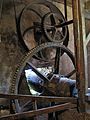
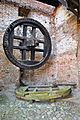
Cast iron mortise wheel with wooden cogs (powered by an external water wheel) meshing with a cast iron gear wheel, connected to a pulley with drive belt. Oil mill in Storkensohn (Haut-Rhin), France.
-
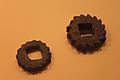
Iron gears from the Han dynasty
-
A single-stage gear reducer
-

A wooden cogwheel driving a lantern pinion or cage gear
-
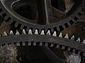
A cast gearwheel (above) meshing with a cogged mortise wheel (below). The wooden cogs are held in place by nails.
-
A bevel gear operating a lock gate
-
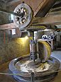
Wooden cogs set in bevel mortise wheels driving a millstone. Note wooden spur gears in the background.
-
Harmonic gearing
-
Wooden gears of a historic windmill
-

Issus coleoptratus (an insect with natural gears!)
-
Line of contact
-
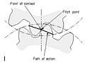
Path of action
-
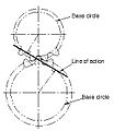
Line of action
-
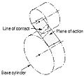
Plane of action
-
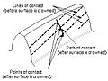
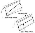
Lines of contact (helical gear)
-
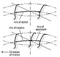
Arc of action
-
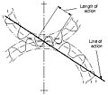
Length of action
-
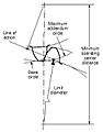
Limit diameter
-
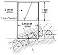
Zone of action
-
Tooth thickness
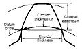
-
Thickness relationships
-
Tooth thickness measurement over pins
-
Span measurement
-
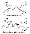
Long and short addendum teeth
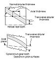
-
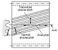
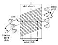
Tooth pitch
-
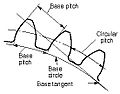
Base pitch relationships
-
Principal pitches
-
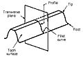
Profile of a spur gear


.jpg)


See Also
 In Spanish: Engranaje para niños
