
Electrical impedance facts for kids


 , across an impedance
  , driving a current
  .
.Electrical impedance is how much a circuit "resists" the flow of electricity. It's like a special kind of resistance that changes depending on how fast the electricity is wiggling back and forth.
You can describe impedance in two main ways:
- Using resistance (R) and reactance (X). Think of it as a map coordinate, like Z = 1 + 1j.
- Using its total "size" (magnitude) and its "angle" (phase). For example, Z = 1.4 at 45 degrees. This means it has a strength of 1.4 ohms and shifts the electricity by 45 degrees.
Contents
What is Electrical Impedance?
Resistance vs. Impedance
You might have heard of resistance. A resistor is a part that slows down electric current. The more resistance it has, the more voltage you need to push a certain amount of current through it. The simple rule for resistance is:  Here, V is the voltage, R is the resistance, and I is the current.
Impedance is similar but a bit more complex. It's about how parts like inductors and capacitors resist changes in current or voltage.
The main difference between resistance and impedance is the idea of "change." This "change" is usually about how often the current or voltage switches direction. We call this the frequency.
For an inductor, the impedance (Z) depends on the frequency (f) and its inductance (L): 
For a capacitor, the impedance (Z) also depends on the frequency (f) and its capacitance (C): 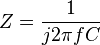
In these formulas, 'j' is a special imaginary number that helps with calculations.  is the constant pi, and 'f' is the frequency. 'L' is for inductance, and 'C' is for capacitance. Both resistance and impedance are measured in ohms, shown by the symbol
  .
.
Impedance changes with frequency. For example, if the frequency is zero (like DC electricity), an inductor acts like a simple wire (zero impedance). A capacitor, however, acts like a break in the circuit (infinite impedance). Most electrical signals are a mix of many frequencies. Each frequency experiences a different impedance.
Just like with resistance, a higher impedance means you need more voltage to get a certain current. The rule for impedance is:  Here, V is the voltage, Z is the impedance, and I is the current.
How Impedance Works
At a very basic level, here's what causes resistance and impedance:
- Resistance happens when electrons flowing through a material bump into atoms. This creates heat.
- Capacitor impedance happens because an electric field is created. Capacitors store energy in this field.
- Inductor impedance happens because a magnetic field is created. Inductors store energy in this field.
An important difference is that resistors turn electrical energy into heat, which is lost. But inductors and capacitors store energy. They can give this energy back to the circuit.
Why Impedance Matters

Imagine you're sending a signal, like sound or data, through a cable. If the impedance of the source (where the signal comes from), the cable, and the device receiving the signal (the load) are not the same, some of the signal can bounce back. This is like an echo. When signals bounce back, it wastes power and can cause problems or interference.
The amount of signal that bounces back can be figured out with a formula: 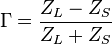 Here,
Here,  (called Gamma) is the reflection amount.
  is the impedance of the source, and
  is the impedance of the load.
Even empty space has an impedance! Light is an electromagnetic wave, and it can travel through space. Empty space has an impedance of about 377 .
What is Phase?

When electricity flows through a simple resistor, the voltage and current go up and down at exactly the same time. We say they are "in phase."
But with impedance, it's different. In a capacitor, the voltage changes after the current. In an inductor, the voltage changes before the current. This difference in timing is called a "phase shift." It's often shown as a quarter of a wavelength, or 90 degrees.
The special imaginary number "j" is used in calculations because it makes working with these phase shifts much easier. It allows engineers to calculate the total impedance of a circuit in a similar way to how they calculate total resistance. For example, if a resistor and an impedance are connected in series, their total impedance is simply R+Z. If they are in parallel, it's (R*Z)/(R+Z).
See also
 In Spanish: Impedancia para niños
