
Multiview orthographic projection facts for kids
Imagine you have a 3D object, like a toy car or a building. How do you draw it on a flat piece of paper so someone else can understand its shape and size perfectly? This is where multiview projection comes in! It's a special way of drawing where you create several flat (two-dimensional) pictures of a 3D object.
Think of it like taking photos of an object from different sides: front, top, and side. These pictures are called primary views. Usually, three views are enough to show all the details needed to build or understand the object. These views are often called the front view, top view, and end view. Sometimes they are also known as plan, elevation, and section.
Contents
How We See Objects in Drawings

To create each picture, we imagine looking at the object from a specific direction. This is like shining a flashlight straight onto the object from far away. The light rays hit the object and then go straight to a flat screen (called a projection plane) behind or in front of it. This creates a 2D shadow or outline of the 3D object.
Usually, we pick six main directions to look at an object, like looking along its main axes:
- Top and Bottom Views: These are called plans. They show how things are arranged on a flat surface, like a floor plan of a house.
- Front and Back Views: These are called elevations. They show the heights of different parts, like the front of a building.
- Left and Right Views: These are also elevations. They show the sides of the object.
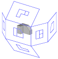
Imagine putting the object inside a clear, six-sided box. Each side of the box becomes a projection plane. We draw the view of the object onto each side. Then, we "unfold" the box so all the drawings are flat on one piece of paper. There are two main ways to unfold this box, which leads to two different drawing standards:
- First-angle projection: Imagine the object is between you (the viewer) and the drawing screen. It's like looking through a transparent object to draw what's behind it. This method is common in many parts of Europe and Asia.
- Third-angle projection: Imagine the drawing screen is between you (the viewer) and the object. It's like drawing what you see directly onto a clear window in front of the object. This method is common in the USA, Japan, Canada, and Australia.
Main Views of an Object
Multiview projections show the main views of an object. Each view looks at the object from a direction parallel to one of its main axes. These main views are called plans and elevations. Sometimes, a drawing shows an object as if it has been cut open to show its inside; these are called sections.
Plan Views

A plan is a view of a 3D object seen from directly above (or sometimes below). Think of it as looking down from a helicopter onto a building. It shows the layout on a horizontal flat surface. For example, the shape of an aircraft wing when seen from above is called its planform.
If you look at a building from above, it's called a roof plan. If you imagine cutting through the walls of a building horizontally and looking down at the floor, that's a floor plan.
Elevation Views

An elevation is a view of a 3D object from the side, as if you are standing in front of it. This means it can be a front elevation, back elevation, left side elevation, or right side elevation.
Elevations are great for showing what the outside of a building or object looks like. Architects use them to show the design of a building's walls, windows, and doors. They are usually drawn to scale, meaning measurements can be taken directly from the drawing.
Developed Elevation
A developed elevation is a special type of elevation. It shows several connected sides of an object as if they have been flattened out. For example, it might show the north and west sides of a building next to each other, even though they are at a right angle in real life. This helps to see all the details of connected surfaces.
Section Views
A section, or cross-section, is a view of a 3D object as if it has been cut through. Imagine slicing a cake in half and looking at the inside; that's a cross-section!
Sections are very useful for showing the inside parts and how they are arranged. In technical drawings, the cut surfaces are often marked with special lines (called crosshatching) to show what kind of material is there.
-
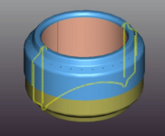
A 3D view of a beverage-can stove with a cross-section shown in yellow.
-
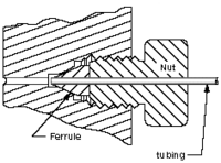
A 2D cross-sectional view of a compression seal.
-

A Porsche 996 cut in half to show its inside.
-
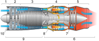
A cross-section of a jet engine, showing its internal parts.


Auxiliary Views
An auxiliary view is a special view that isn't one of the main six views (front, top, side). These views are used when an object has a slanted or angled surface. By looking straight at that slanted surface, the auxiliary view shows its true size and shape. This is helpful for measuring or drilling holes correctly on angled parts.
Understanding First-Angle and Third-Angle Projection

Both first-angle and third-angle projections create the same six views of an object. The only difference is how these views are arranged on the paper.
First-Angle Projection
In first-angle projection, imagine the object is floating in front of the drawing planes. The drawing planes are like opaque walls. Each view of the object is drawn on the wall that is farthest from you. So, if you look at the front of the object, the front view is drawn on the back wall. Then, you unfold the box to see all the drawings on the inside walls.
-
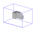
An object inside a box.
-
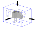
Views of the object are projected onto the walls using first-angle projection.
-
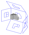
The box unfolds around the object.
-
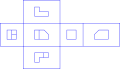
The final arrangement of views in first-angle projection.


Third-Angle Projection

In third-angle projection, imagine the object is behind the drawing planes. The drawing planes are like transparent windows. Each view of the object is drawn on the window that is closest to you. So, if you look at the front of the object, the front view is drawn directly on the front window. Then, you unfold the box to see all the drawings on the outside walls.
-
The object inside a box.
-
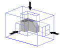
Views are projected onto the walls using third-angle projection.
-
The box unfolds.
-
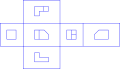
The final arrangement of views in third-angle projection.


Where Each Method is Used

First-angle projection is used in most parts of the world, including many countries in Europe and Asia (but not Japan).
Third-angle projection is most common in the USA, Japan, Canada, and Australia.
To avoid confusion when drawings are shared between different countries, a special symbol is often used on engineering drawings. This symbol shows whether the drawing uses first-angle or third-angle projection. It looks like a cone cut in half.
- In first-angle projection, the symbol shows the smaller end of the cone farther away from the circles.
- In third-angle projection, the symbol shows the smaller end of the cone closer to the circles.
See also
 In Spanish: Sistema diédrico para niños
- Architectural drawing
- Cross section (geometry)
- Engineering drawing
- Graphical projection
- Plans (drawings)
