Pascal's calculator facts for kids
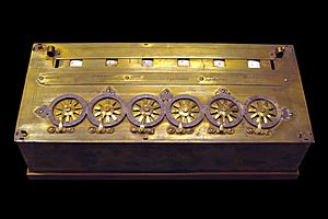
The Pascal's calculator (also called the arithmetic machine or Pascaline) was a special mechanical calculator. It was invented by Blaise Pascal in 1642. Pascal created this machine because his father, a tax supervisor, had to do many difficult math problems by hand. The Pascaline was designed to add and subtract numbers directly. It could also multiply and divide by doing repeated additions or subtractions.
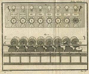
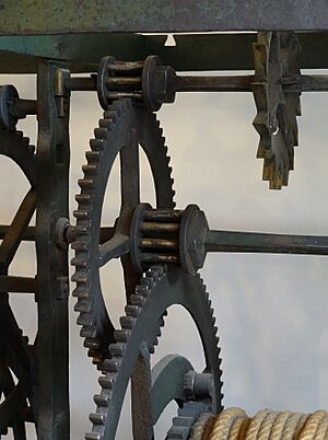
One of the best parts of Pascal's calculator was its carry mechanism. This part would automatically add 1 to the next number dial when the first dial went from 9 to 0. This smart design made each number dial work on its own. This meant that carries could quickly move from one digit to the next, no matter how many numbers the machine could handle. Pascal also made a special type of gear, called a lantern gear, much smaller. These gears were used in large turret clocks and water wheels. This change made the calculator strong enough to handle someone turning the dials without much extra rubbing or friction.
Pascal designed the machine in 1642. After making 50 different test versions, he showed his invention to the public in 1645. He dedicated it to Pierre Séguier, who was then the top legal official in France. Over the next ten years, Pascal built about twenty more machines. Many of these were better than his first design. In 1649, King Louis XIV of France gave Pascal a special royal privilege. This was like a patent, giving him the only right to design and make calculating machines in France. Today, nine Pascal calculators still exist. Most of them are on display in museums in Europe.
Many calculators made later were either inspired by Pascal's work or came from similar ideas. Gottfried Leibniz invented his Leibniz wheels after 1671. He had tried to add an automatic multiplication feature to the Pascaline. In 1820, Thomas de Colmar created his arithmometer. This was the first mechanical calculator that was strong and reliable enough for daily use in an office. It's not clear if he ever saw Leibniz's machine. However, he either invented the step drum again or used Leibniz's idea.
Contents
How the Pascaline Was Invented
Blaise Pascal started working on his calculator in 1642. He was only 18 years old. He was helping his father, who was a tax collector. Pascal wanted to create a device that could make his father's work easier. In 1649, Pascal received a Royal Privilege. This gave him the only right to make and sell calculating machines in France.
By 1654, Pascal had sold about twenty machines. Only nine of these machines are known to exist today. However, the Pascaline was expensive and complicated to make. This made it hard to sell more. So, production stopped that year. By then, Pascal had started studying religion and philosophy. His studies led to famous works like Lettres provinciales and Pensées.
The 300th birthday celebration of Pascal's calculator happened during World War II. At that time, France was occupied by Germany. So, the main celebration was held in London, England. Speeches at the event praised Pascal's practical achievements. He was already known for his pure math work. People also talked about his creative imagination. Both the machine and its inventor were far ahead of their time.
How the Calculator Worked
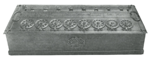
The calculator had metal wheels with spokes. The numbers 0 through 9 were shown around the edge of each wheel. To enter a number, you would put a pen or stylus in the space between the spokes. Then, you would turn the dial until it hit a metal stop at the bottom. This was similar to how old telephone dials worked. The number you entered would then show up in small windows at the top of the calculator. To add a second number, you would just dial it in. The total sum of both numbers would then appear in the display.
Each dial had a small display window right above it. This window showed the current number stored for that position. There was also a horizontal bar. You could slide this bar up to see the actual numbers. Or, you could slide it down to see the "complement" numbers. These complement numbers were used for subtraction.
Because the gears only turned in one direction, you couldn't directly add negative numbers. To subtract one number from another, a method called nine's complement was used. The only real differences between adding and subtracting were where the display bar was set and how the first number was entered.
For a wheel with 10 numbers (0-9), the outside wheel was numbered from 0 to 9. The numbers were written in a decreasing order as you moved clockwise. To add a 5, you would put a stylus between the spokes around the number 5. Then, you would rotate the wheel clockwise all the way to the stop. The number shown in the display window would go up by 5. If a carry happened, the display window to its left would go up by 1. To add 50, you would use the tens input wheel. This was the second dial from the right on a decimal machine. To add 500, you would use the hundreds input wheel, and so on.
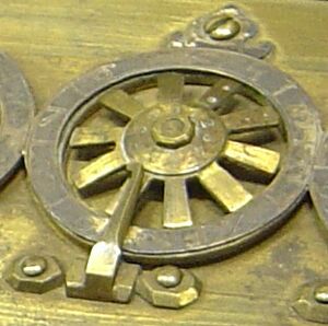
On all the known Pascaline machines, two nearby spokes on the wheels had special marks. These marks were different on each machine. On the wheel shown in the picture, they are drilled dots. On other machines, they might be carved or just scratches.
These marks helped to set the number cylinder to its highest number. This was done to get it ready to be reset to zero. To do this, the operator would put the stylus between these two marked spokes. Then, they would turn the wheel all the way to the stop. This worked because each wheel was directly connected to its display cylinder. It would automatically turn by one during a carry operation.
Some machines had inner wheels with "complements." These were used to enter the first number when doing subtraction. They were in the center of each spoked metal wheel and turned with it. On a decimal machine, the numbers 0 through 9 were carved clockwise. Each number was placed between two spokes. This allowed the operator to enter its value directly into the complement window. They would do this by putting their stylus between the spokes and turning the wheel clockwise to the stop. The marks on two nearby spokes were next to the 0 on this inner wheel.
On some machines, a small "quotient wheel" was placed above each main wheel on the display bar. Operators would set these quotient wheels. They had numbers from 1 to 10 marked on their edges. Quotient wheels seemed to be used during division. They helped remember how many times a number was subtracted at each step.
Inside the Machine: Gears and Carries
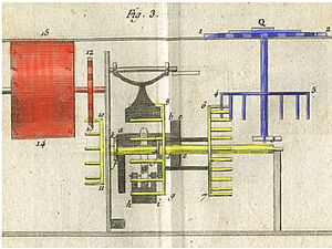
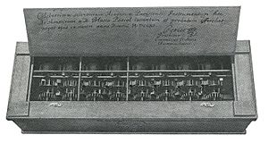
Pascal made 50 different test versions before he decided on his final design. We know he started with a clock-like mechanism. It used springs and was very simple. It was used many times and kept working. But he kept trying to make the whole system more reliable and strong. He eventually used a part from very large clocks. He made smaller versions of the strong gears found in a turret clock, called a lantern gear. This idea came from water wheel mechanisms. These gears could easily handle the force of someone turning the dials.
Pascal also used a "pawl and ratchet" system in his design. The pawl stops the wheel from turning backward when someone inputs a number. It also helps to perfectly position the display wheel and the carry mechanism for the next number. Because of this, every number displayed was perfectly centered. Each digit was also precisely ready for the next math problem. If an operator dialed a six on an input wheel, this mechanism would move six times.
The Carry Mechanism: The Sautoir
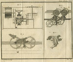
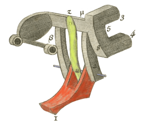
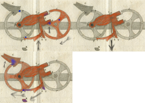
The "sautoir" is the most important part of the Pascaline's carry mechanism. Pascal wrote that a machine with 10,000 wheels would work just as well as one with two wheels. This is because each wheel works on its own. When it's time to carry a number, the sautoir, pulled only by gravity, "jumps" to the next wheel without touching the other wheels. During its fall, the sautoir acts like an acrobat jumping from one trapeze to another without the trapezes touching. (The word "sautoir" comes from the French word sauter, meaning "to jump.") All the wheels (including gears and sautoir) have the same size and weight, no matter how many numbers the machine can handle.
Pascal used gravity to prepare the sautoirs. You had to turn a wheel five steps (for example, from 4 to 9) to fully prepare a sautoir. But the carry transfer would only move the next wheel one step. This meant a lot of extra energy was stored up when a sautoir was prepared.
All the sautoirs were prepared either by someone inputting a number or by a carry from another wheel. To reset a machine with, say, 10,000 wheels (if one existed), the operator would set every wheel to its highest number. Then, they would add 1 to the very first wheel on the right. The carry would then turn each input wheel one by one, very quickly, like a Domino effect. All the display numbers would then reset to zero.
The carry process had three main steps:
- The first step happens when the display number goes from 4 to 9. Two small pins lift the sautoir. At the same time, a kicking pawl is pulled up. It uses a pin on the next wheel as a guide. But it doesn't move that wheel yet. During this step, the active wheel touches the sautoir, but it doesn't move the next wheel. So, the state of the next wheel doesn't affect the active wheel.
- The second step starts when the display number goes from 9 to 0. The kicking pawl passes its guiding pin. Its spring then positions it above this pin, ready to push it. The sautoir keeps moving up, and then the second carry pin lets it drop. The sautoir falls by its own weight. During this step, the sautoir and the two wheels are completely separate.
- The kicking pawl pushes the pin on the next wheel and starts turning it. The upper pawl/ratchet moves to the next spot. The operation stops when a part hits a buffer stop. The upper pawl/ratchet puts the whole receiving mechanism in the right place. During this step, the sautoir, which is no longer touching the active wheel, adds one to the next wheel.
How to Use the Pascaline
The Pascaline was a direct adding machine. This means it didn't have a crank. The value of a number was added to the total as you dialed it in. By moving a display bar, the operator could see either the number stored in the calculator or its "complement" value. Subtractions were done like additions, using a special math trick called 9's complement.
Using 9's Complement for Subtraction
The 9's complement of any single-digit number d is 9 minus d. So, the 9's complement of 4 is 5. The 9's complement of 9 is 0.
For a decimal machine with many dials, the 9's complement of a number A is calculated as:
This means that the 9's complement of (A-B) is:
Simply put, the 9's complement of a subtraction (A-B) is the same as adding the 9's complement of A to B. This trick works for numbers with different bases too, like those used in surveying or accounting machines.
This idea can also be used for more complex subtractions:
Here's how this trick applied to the Pascaline:
| First Step | First, you enter the complement of the first number (the one you're subtracting from). You can use the inner wheels of complements or dial the complement directly. The display bar is moved to show the complement's window. This way, you see the actual number because the complement of a complement is the original number. |
|---|---|
| Second Step | Then, the second number is dialed in. This adds its value to the total. |
| Result | The answer (A-B) is shown in the complement window. This is because the complement of the complement of (A-B) is (A-B). You can repeat the last step as long as the number you are subtracting is smaller than the number currently shown. |
Clearing the Machine
The machine had to be reset to zero before each new calculation. To do this, the operator would set all the wheels to their highest number. They would use the marks on two adjacent spokes to do this. Then, they would add 1 to the wheel on the far right.
The way Pascal chose to reset his machine was very demanding. It made a carry travel all the way through the machine. This showed, before every operation, that the machine was working perfectly. This is a sign of how well the Pascaline was made. Even though people criticized the machine in the 1700s, no one ever mentioned a problem with the carry mechanism. This feature was tested every time the machine was reset.
| Resetting | Set all the wheels to their highest number using the marks on two adjacent spokes. Every single wheel is now ready for a carry transfer. |
|
||||||||||
|---|---|---|---|---|---|---|---|---|---|---|---|---|
| Add 1 to the wheel on the far right. Each wheel sends its sautoir to the next one. The zeros appear one after another, like a domino effect, from right to left. |
|
Adding Numbers
To add numbers, the display bar was moved closest to the edge of the machine. This showed the direct value of the total.
After clearing the machine to zero, numbers were dialed in one after the other.
Here's how to calculate 12,345 + 56,789 = 69,134:
| Addition | The machine is at zero. The operator enters 12,345. |
|
||||||||||
|---|---|---|---|---|---|---|---|---|---|---|---|---|
| The operator enters the second number: 56,789. If they start with the rightmost number, the second wheel will go from 4 to 5 when dialing the 9, because of a carry. |
|
Subtracting Numbers
To subtract numbers, the display bar was moved closest to the center of the machine. This showed the "complement" value of the total.
The machine would hold the complement of the first number. After adding the second number, it would hold the complement of the answer. By showing this in the complement window, the operator would see the correct answer. It felt like an addition, since the only differences were the display bar position and how the first number was entered.
Here's how to calculate 54,321 - 12,345 = 41,976:
| Change Display | Move the display bar down. This uncovers the complement part of each number cylinder. From now on, every number dialed into the machine adds to the total, but it makes the number shown in the complement window go down. |
|
||||||||||
|---|---|---|---|---|---|---|---|---|---|---|---|---|
| Subtraction | Enter the 9's complement of the first number (54,321). This is 45,678. You can use the inner wheels of complements or dial it directly. |
|
||||||||||
| Dial the number you are subtracting (12,345) on the spoked metal wheels. This is an addition step. The answer, 41,976, is shown in the 9's complement window. |
|
Different Types and Uses
Pascalines came in different versions. Some were for decimal numbers (like our regular numbers). Others were for non-decimal numbers. You can see both types in museums today. They were made for scientists, accountants, and surveyors. The simplest Pascaline had five dials. Later versions had up to ten dials.
The money system in France back then used livres, sols, and deniers. There were 20 sols in a livre and 12 deniers in a sol. Length was measured in toises, pieds, pouces, and lignes. There were 6 pieds in a toise, 12 pouces in a pied, and 12 lignes in a pouce. Because of this, the Pascaline needed wheels that could count in bases of 6, 10, 12, and 20. The non-decimal wheels were always placed before the decimal part.
For an accounting machine, the decimal part counted livres. The other wheels counted sols (base 20) and deniers (base 12). For a surveyor's machine, the decimal part counted toises. The other wheels counted pieds (base 6), pouces (base 12), and lignes (base 12). Scientific machines only had decimal wheels.
| Machine type | Other wheels | 4th | 3rd | 2nd | 1st |
|---|---|---|---|---|---|
| Decimal / scientific | base 10 Ten thousands |
base 10 Thousands |
base 10 Hundreds |
base 10 Tens |
base 10 Units |
| Accounting | base 10 Hundreds |
base 10 Tens |
base 10 Livres |
base 20 Sols |
base 12 Deniers |
| Surveying | base 10 Tens |
base 10 Toises |
base 6 Pieds |
base 12 Pouces |
base 12 Lignes |
The metric system, which we use today, was adopted in France on December 10, 1799. By then, Pascal's basic design had inspired other inventors. However, their machines also didn't sell very well.
Where Are They Now?
Most of the Pascaline machines that have survived over the centuries are the accounting type. Seven of them are in European museums. One belongs to the IBM company, and one is owned by a private collector.
| Location |
Country |
Machine Name |
Type |
Wheels |
Configuration |
Notes |
|---|---|---|---|---|---|---|
| CNAM museum Paris |
France | Chancelier Séguier | Accounting | 8 | 6 x 10 + 20 + 12 | |
| CNAM museum Paris |
France | Christina, Queen of Sweden | Scientific | 6 | 6 x 10 | |
| CNAM museum Paris |
France | Louis Périer | Accounting | 8 | 6 x 10 + 20 + 12 | Louis Périer, Pascal's nephew, gave it to the Académie des sciences de Paris in 1711. |
| CNAM museum Paris |
France | Late (Tardive) | Accounting | 6 | 4 x 10 + 20 + 12 | This machine was put together in the 1700s using old parts. |
| Musée Henri Lecoq Clermont-Ferrand |
France | Marguerite Périer | Scientific | 8 | 8 x 10 | Marguerite (1646–1733) was Pascal's goddaughter. |
| Musée Henri Lecoq Clermont-Ferrand |
France | Chevalier Durant-Pascal | Accounting | 5 | 3 x 10 + 20 + 12 | This is the only known machine that came with a box. It is also the smallest machine. Was it made to be carried around? |
| Mathematisch-Physikalischer Salon, Dresden | Germany | Queen of Poland | Accounting | 10 | 8 x 10 + 20 + 12 | The second wheel from the right has a wheel with 10 spokes inside a fixed wheel with 20 parts. This might be due to a bad repair. |
| Léon Parcé collection | France | Surveying | 8 | 5 x 10 + 6 + 12 + 12 | This machine was bought as a broken music box in a French antique shop in 1942. | |
| IBM collection | USA | Accounting | 8 | 6 x 10 + 20 + 12 |
Pascaline's Achievements
The Pascaline was the first calculating machine shown to the public in its time. It also holds many other important achievements:
- It was the only working mechanical calculator in the 1600s.
- It was the first calculator with a controlled carry mechanism. This allowed it to correctly carry numbers across many digits.
- It was the first calculator used in an office (Pascal's father used it for taxes).
- It was the first calculator sold to people (about twenty machines were built).
- It was the first calculator to get a patent (the royal privilege of 1649).
- It was the first calculator described in an encyclopaedia (by Diderot & d'Alembert in 1751).
- It was the first calculator sold by a distributor.
Other Early Calculators
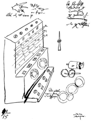
In 1957, a writer named Franz Hammer found two letters. These letters were written by Wilhelm Schickard to his friend Johannes Kepler in 1623 and 1624. They contained drawings of a calculating clock that no one knew about before. This clock was made twenty years before Pascal's work. The 1624 letter said that the first machine built by a professional was destroyed in a fire. Schickard then gave up on his project. Later, people found that Schickard's drawings had actually been published many times since 1718.
A math professor, Bruno von Freytag Loringhoff, built the first copy of Schickard's machine. But he had to add wheels and springs to make it work. These details were not in Schickard's letters or drawings. After copies were built, a problem was found in how Schickard's machine worked, based on his original notes. Schickard's machine used clock wheels. These were made stronger and heavier so they wouldn't break when someone used them. Each number used a display wheel, an input wheel, and a middle wheel. During a carry, all these wheels connected with the wheels of the next digit. The total rubbing and weight of all these wheels could "potentially damage the machine if a carry needed to go through many digits, for example, adding 1 to 9,999."
Pascal's great invention was that his calculator was designed so each input wheel worked completely on its own. Carries were passed one after another. Pascal chose a way to reset his machine that sent a carry all the way through it. This was the hardest thing a mechanical calculator could do. It proved, before every calculation, that the Pascaline's carry mechanism worked perfectly. This shows how good the Pascaline was. Even with criticisms in the 1700s, no one ever said there was a problem with the carry mechanism. This feature was tested every time the machines were reset.
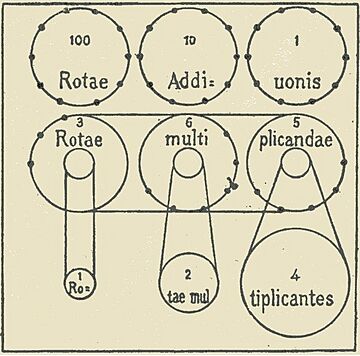
Gottfried Leibniz started working on his own calculator after Pascal died. He first tried to build a machine that could multiply automatically while sitting on top of the Pascaline. He wrongly thought that all the dials on Pascal's calculator could be used at the same time. Even though this didn't work, it was the first time a "pinwheel" was drawn and used in a calculator design.
He then created a different design, the Stepped Reckoner. This machine was meant to add, subtract, and multiply automatically. It could also divide with the operator's help. Leibniz worked for forty years to perfect this design. He made two machines, one in 1694 and one in 1706. Only the 1694 machine is known to exist today. It was found at the end of the 1800s, after being forgotten in an attic at the University of Göttingen for 250 years.
A German calculator inventor, Arthur Burkhardt, was asked to try to get Leibniz's machine working. He said it worked well, except for the carry process. He noted that "especially with many carries, the operator had to check the result and manually fix any possible errors." Leibniz didn't manage to create a calculator that worked perfectly. But he did invent the Leibniz wheel, which was a new idea for mechanical calculators. He was also the first to use sliders to enter the first number and a movable part for the results.
There were five more attempts to design "direct entry" calculating machines in the 1600s. These included designs by Tito Burattini, Samuel Morland, and René Grillet.
Around 1660, Claude Perrault designed an abaque rhabdologique. This is often mistaken for a mechanical calculator because it had a carry mechanism between numbers. But it was actually an abacus. It required the operator to handle the machine differently when a carry happened.
Pascal's calculator was the most successful mechanical calculator made in the 1600s for adding and subtracting large numbers. The Stepped Reckoner had a problem with its carry mechanism after more than two carries in a row. Other devices had carry mechanisms that couldn't handle many digits, or they had no carry mechanism between the numbers at all.
Calculating machines didn't become truly useful for business until 1851. That's when Thomas de Colmar released his simpler arithmometer. He worked on it for thirty years. It was the first machine strong enough for daily use in an office. The Arithmometer was designed using Leibniz wheels. It first used Pascal's 9's complement method for subtractions.
More About Calculators
- Adding machine
- Stepped reckoner
- Arithmometer
- Comptometer
- Difference engine
- Analytical engine
- Z1 (computer)
 | Lonnie Johnson |
 | Granville Woods |
 | Lewis Howard Latimer |
 | James West |


