Thyristor facts for kids
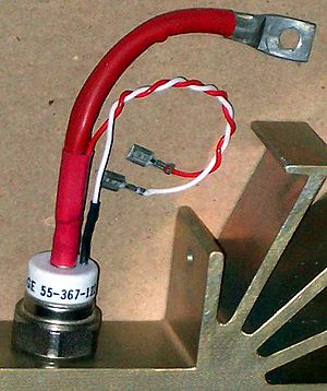
Thyristor
|
|
| Type | Active |
|---|---|
| First production | 1956 |
| Pin configuration | anode, gate and cathode |
| Electronic symbol | |
 |
|
A thyristor is a special electronic part. It's made of solid materials, like a semiconductor device. It has four layers of different materials (P-type and N-type) stacked together.
Thyristors are mostly used for controlling large amounts of electric power. Think of them as a super-fast, super-strong switch. They can be either completely ON or completely OFF. Once a small electric signal (a "trigger") is sent to its "gate" part, it turns ON. It stays ON until the power flowing through it stops or reverses direction.
Some people use the words "thyristor" and "silicon-controlled rectifier" (SCR) to mean the same thing. Others say thyristors are a bigger family of devices that include SCRs.
The first thyristors were sold in 1956. Because they can handle a lot of power with a small size, they are used in many places. This includes light dimmers, electric motor speed controls, and even in huge systems that send electricity over long distances (like high-voltage direct-current power transmission).
Thyristors are great for switching power on and off. Unlike transistors, which can be partly on, a thyristor is either fully on or fully off. This makes them perfect for switching, but not for making sounds louder (like an amplifier).
Contents
How a Thyristor Works
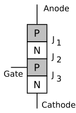
A thyristor is a four-layer electronic device. It has three connections, called "terminals." These layers are made of alternating N-type and P-type materials, like a P-N-P-N sandwich.
The two main connections are called the anode and the cathode. They are at the ends of the four layers. The third connection is called the gate. It's like a control wire. It's connected to the P-type material near the cathode.
You can imagine a thyristor working like two bipolar junction transistors connected in a special way. This setup makes it "latch" on once it's triggered.
Thyristors have three main states:
- Reverse blocking mode: This is when voltage is applied in a way that a normal diode would block it. The thyristor stays OFF.
- Forward blocking mode: Voltage is applied in the direction that would make a diode turn ON. But the thyristor stays OFF because it hasn't been triggered yet.
- Forward conducting mode: The thyristor has been triggered and is now ON. It will stay ON until the electric current flowing through it drops very low. This low current is called the "holding current."
The Gate Terminal's Job
A thyristor has three special connections inside called "p-n junctions." Let's call them J1, J2, and J3.
When the anode has a positive voltage compared to the cathode, and no voltage is on the gate:
- Junctions J1 and J3 are ready to conduct.
- But junction J2 is blocking the flow of electricity. So, the thyristor stays OFF.
If you increase the voltage between the anode and cathode enough, junction J2 will break down. Then, the thyristor suddenly turns ON and starts conducting electricity. This is called the "breakdown voltage."
However, you can turn the thyristor ON much more easily! If you apply a small positive voltage to the gate terminal, it helps junction J2 break down at a much lower anode-cathode voltage. This lets you switch the thyristor ON quickly and exactly when you want.
Once the thyristor is ON, it stays ON. The gate voltage doesn't matter anymore. It will only turn OFF if:
- The voltage across the anode and cathode is removed.
- The current flowing through it drops below a certain level (the "holding current").
So, the gate signal can be just a short burst of electricity. This burst tells the thyristor to turn on, and then it takes over from there.
How Thyristors Switch
Once a regular thyristor is turned ON by its gate, it stays ON. It doesn't need a continuous signal to the gate. This is true as long as the current flowing through it is above a certain level called the "latching current."
The thyristor will stay ON as long as the anode is positive. It can't be turned OFF unless the current drops below the "holding current." The latching current is always higher than the holding current.
A thyristor can be turned OFF if the circuit makes the anode negative. This is called "natural commutation" or "line commutation." In some cases, another thyristor is used to force the first one to turn off. This is called "forced commutation."
After the current drops below the holding current, there's a short delay before the thyristor is truly ready to block voltage again. This delay is called the "turn-off time" (tQ). If you try to turn it on too soon, it might accidentally switch on by itself.
For very fast applications, like those used in higher frequencies than home electricity, special "fast thyristors" are needed. These are made by adding tiny amounts of certain metals or by using special radiation treatments. This helps the leftover electrical charges disappear faster, allowing the thyristor to turn off more quickly.
History of the Thyristor
The idea for the silicon-controlled rectifier (SCR), which is a type of thyristor, came from William Shockley in 1950. It was further developed in 1956 by engineers at General Electric (G.E.), led by Gordon Hall. Frank W. "Bill" Gutzwiller from G.E. helped make it a product people could buy.
The Institute of Electrical and Electronics Engineers (IEEE) recognized this invention as a very important step in technology.
What's in a Name?
Before thyristors, there was an older electronic device called a "thyratron." It was a gas-filled tube that could also switch large currents with a small control voltage. The name "thyristor" comes from combining "THYRatron" and "transISTOR."
Where Thyristors Are Used
Thyristors are mainly used in places where there are high electric currents and voltages. They are often used to control alternating currents (AC). This is because AC changes direction regularly, which helps the thyristor turn off automatically. This is called "zero cross" operation.
You can find thyristors in:
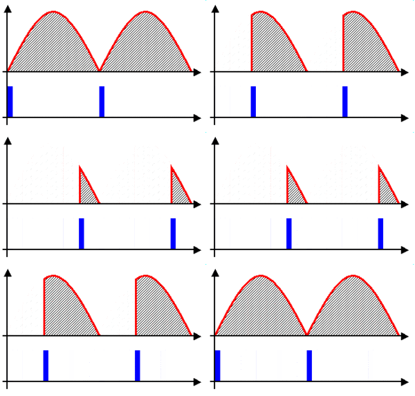
- Light dimmers: They control how much electricity goes to a light bulb, making it brighter or dimmer. They replaced older, less efficient ways of dimming lights.
- Motor speed controls: They can adjust the speed of electric motors.
- Power supplies: In some digital devices, thyristors act like a super-fast circuit breaker. If the power supply voltage gets too high, the thyristor quickly shorts the power to the ground. This protects sensitive parts from damage. This is called a "crowbar" circuit.
- Photography flashes: They are a key part of how camera flashes work.
Snubber Circuits
Sometimes, a thyristor can accidentally turn ON if the voltage across it rises too quickly, even without a gate signal. This is called "dV/dt triggering."
To stop this, a special circuit called a "snubber" is used. It's usually a resistor and a capacitor connected together across the thyristor. The snubber helps to slow down any sudden voltage changes, preventing the thyristor from turning on by mistake.
HVDC Electricity Transmission
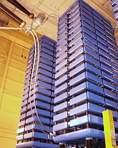
Modern thyristors can switch huge amounts of power, sometimes millions of watts! Because of this, "thyristor valves" are at the heart of high-voltage direct current (HVDC) systems. These systems are used to send electricity over very long distances.
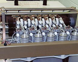
In HVDC systems, many thyristors are connected together in a series. They are often cooled with special water. These groups of thyristors form large "valves" that help change AC electricity to DC, and then back to AC at the other end of the transmission line.
How Thyristors Compare to Other Devices
TRIAC
A regular thyristor only lets electricity flow in one direction, like a diode. This means it can't be used directly with AC current (which flows in both directions).
A similar device called a TRIAC can work in both directions. It's like having two thyristors connected back-to-back. However, this can sometimes cause problems with certain types of electrical loads, making it hard for the TRIAC to turn off properly. To fix this, TRIACs often need a "snubber" circuit, just like thyristors.
You can also use two separate thyristors connected in opposite directions instead of a TRIAC. This makes sure they turn off correctly, but it also means you need two control circuits instead of one.
Power MOSFETs and IGBTs
While thyristors are great for very high power, for lower and medium power uses (from a few watts to tens of thousands of watts), other devices are often used. These include Power MOSFETs and IGBTs.
These devices are better at switching on and off very quickly. Thyristors can be a bit slow because of how they conduct electricity. MOSFETs, for example, are much faster because they use only one type of electrical charge carrier.
Also, thyristors are only fully ON or fully OFF. MOSFETs and IGBTs can be controlled to be partly ON, which gives more flexible control in some applications. However, special types of thyristors, like the GTO thyristor and IGCT, have been developed to address this "fully ON/OFF" limitation.
What Can Go Wrong
Thyristor makers provide rules for how much voltage and current a thyristor can handle safely. If you go beyond these limits, the thyristor can break.
Some common ways thyristors can fail include:
- Too fast turn-on current: If the current tries to flow through the thyristor too quickly when it's turning on, it can get damaged.
- Accidental turn-on: If the voltage across the thyristor rises too fast (dV/dt), it can accidentally turn on even without a gate signal. This is why snubber circuits are important.
Silicon Carbide Thyristors
Recently, some companies have started making thyristors using a material called silicon carbide (SiC). These special thyristors can work in very hot places, up to 350 degrees Celsius (662 degrees Fahrenheit). This makes them useful for high-temperature electronics.
Types of Thyristors
There are many different types of thyristors, each designed for specific jobs:
- SCR – This is the most common type of thyristor.
- GTO – A special thyristor that can be turned OFF by a signal to its gate.
- IGCT – A very powerful type of GTO.
- MCT – A thyristor that uses FETs for control.
- TRIAC – A thyristor-like device that can switch AC current in both directions.
- Quadrac – Combines a DIAC (a trigger device) and a TRIAC in one package.
- RCT – Has a built-in diode that allows current to flow in the reverse direction.
- SITh – Can shut down the current flow from the anode.
Reverse Conducting Thyristor
A reverse conducting thyristor (RCT) has a diode built right into it. This means it can't block current flowing in the reverse direction. RCTs are useful when a reverse diode is needed in the circuit. Because the thyristor and the diode don't conduct at the same time, they don't both get hot at once. This makes them easier to cool. RCTs are often used in devices that change electricity frequency or inverters.
Photothyristors
Photothyristors are special thyristors that are turned ON by light instead of an electrical signal. The advantage of these is that they are not affected by electrical noise, which can cause other thyristors to turn on by mistake.
A light-triggered thyristor (LTT) has a part that is sensitive to light. Light, usually infrared, is sent to it through a thin glass fiber (optical fiber). Since no electrical wires are needed to trigger it, LTTs are very useful in HVDC systems where voltages are extremely high.
Two common types are the light-activated SCR (LASCR) and the light-activated TRIAC. A LASCR turns on when light hits it. It stays on until the power is removed or the voltage reverses. A light-activated TRIAC is similar but works with alternating currents.
See also
 In Spanish: Tiristor para niños
- Thyristor-controlled reactor
- Insulated-gate bipolar transistor
- Latch-up
- Quadrac
- Thyratron
- Thyristor drive
 | Aurelia Browder |
 | Nannie Helen Burroughs |
 | Michelle Alexander |


