Toddbrook Reservoir facts for kids
Quick facts for kids Toddbrook Reservoir |
|
|---|---|

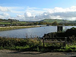
Looking southeast towards the dam, from the northern corner
|
|
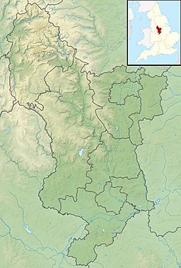
| Location | High Peak, Derbyshire |
| Coordinates | 53°19′30″N 1°59′37″W / 53.32500°N 1.99361°W |
| Type | reservoir |
| Catchment area | 1,700 ha (4,200 acres) |
| Basin countries | United Kingdom |
| Surface area | 14.6 ha (36 acres) |
| Max. depth | 23.8 m (78 ft) |
| Water volume | 1,288,000 cubic metres (283,000,000 imp gal) |
| Surface elevation | 185.69 m (609.2 ft) |
| Islands | None |
Toddbrook Reservoir is a large lake built by people, called a reservoir. It opened in 1838 and helps supply water to the Peak Forest Canal. You can find it above the town of Whaley Bridge in the Derbyshire High Peak area of England.
This reservoir is a special place for nature, known as a Site of Special Scientific Interest (SSSI). It's home to many animals like herons and ducks, as well as different kinds of fish. Rare mosses and liverworts also grow along its edges, especially small plants that like mud that appears at certain times of the year. People enjoy Toddbrook Reservoir for sailing and angling (fishing). A walking path, the Peak District Boundary Walk, goes around the eastern side of the reservoir. The Canal & River Trust owns the reservoir. It works with Combs Reservoir to feed water into the Peak Forest Canal system.
The reservoir gets its water from the Todd Brook stream. This stream collects water from a large area, including the moorland on Shining Tor and farms near Kettleshulme village. Water flows into the reservoir on its north side through a small waterfall. Sometimes, if there isn't enough rain, the reservoir doesn't get much new water. This can make the water level drop, especially in summer.
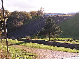
The dam at Toddbrook Reservoir is made of earth with a special clay core inside. It's about 310 meters long. In August 2019, heavy rain caused some concrete panels on its spillway (a channel for excess water) to break. This led to people being asked to leave parts of Whaley Bridge because of worries about the dam.
Contents
Building the Toddbrook Dam
As more boats used the Peak Forest Canal, the water from Combs Reservoir wasn't enough. Even getting water from another canal's reservoir didn't solve the problem. So, in 1834, the canal company decided to build Toddbrook Reservoir.
Planning and Early Problems
Planning the reservoir wasn't easy. There were concerns about the ground because of old coal mines under the valley. Different places for the dam were looked at. John Wood made the first plans, but other expert engineers, like Robert Matthews and Nicholas Brown, changed them.
Building contracts were given out in 1836. But geological problems continued, and the dam's location was changed again in 1837. At one point, they even thought about stopping the project because they found a way to get water to the canal without the reservoir.
Completing the Dam
However, construction continued with new plans. William Mackenzie oversaw the work. The reservoir was finished by June 1841. At 24 meters tall, the dam was the highest ever built for a canal reservoir at that time.
The dam's core was supposed to be made of a special clay. Later checks in the 1900s made people wonder if it was built exactly as planned. The dam wall is supported by earth banks on both sides. Underneath the dam, the ground has layers of sand, gravel, and different kinds of rock and coal.
Dam Maintenance and Repairs
For many years, local coal mining was a worry for the dam. As early as 1880, there were complaints that water was leaking into coal mines. The railway company, which owned the canal, even bought the coal under the reservoir to stop mining there.
Finding and Fixing Leaks
In 1931, a leak was found at the bottom of the dam. It was fixed by filling a dip in the dam's slope. In 1975, when the water level was low, another dip appeared in the same spot. This led to the dam being watched closely.
By 1977, the dam had sunk a little. The reservoir was emptied, and a large hole was found. It was partly filled with mud and even a tree that seemed to have been pulled in by the water flow. More checks were done between 1978 and 1980.
In 1981, a 1.2-meter wide stone tunnel was found. It was likely built into the dam when it was first made to move groundwater. Leaks had developed around it, creating a weak spot. Repairs were made, and a layer of waterproof clay was added to the dam's face. The clay core was also strengthened. The reservoir was refilled in December 1983.
Spillway Damage and Upgrades
In December 1964, heavy rain damaged the dam's spillway. The water level rose very high but thankfully didn't go over the main dam wall. However, the large amount of water damaged the spillway channel and started to wear away the bank at the dam's base. The damage was fixed in 1965. But studies showed the spillway wasn't big enough for future floods. It was noted that similar damage had happened to other dams where the spillway sent water to the dam's base.
In 1969, a new concrete spillway was built on the dam's downstream side. This new weir was made by adding concrete to the earth bank to protect it from flowing water. It was placed above the old spillway. In the 1980s, British Waterways did more big repairs to fix leaks caused by mine shafts around the dam. A tunnel was also built under the reservoir's beach area. A stone marker used to show its location but was moved in 2009.
Recent Inspections and Repairs
The reservoir was partly emptied in 2009 for a check-up. Then, in 2010, it was fully emptied for major repairs that cost £500,000. Fish were moved to other places before work began. Repairs included fixing the stone wall of the dam.
Other work involved fixing 100-year-old pipes that control water flow into the Peak Forest Canal. This included:
- Cleaning mud and dirt from pipe openings.
- Removing old valves and connections.
- Cleaning and checking the old pipes.
- Lining the old pipes with a new resin "sock" that was hardened with ultraviolet lights.
- Replacing valves.
- Testing the new system.
- Replacing screens at the water intakes.
 | Calvin Brent |
 | Walter T. Bailey |
 | Martha Cassell Thompson |
 | Alberta Jeannette Cassell |


