kids encyclopedia robot

USB-C facts for kids

Kids Encyclopedia Facts
Quick facts for kids
USB-C
USB Type-C icon.svg
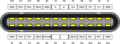
Pins of the USB-C connector
Type Digital audio / video / data connector / power
Production history
Designer USB Implementers Forum
Designed 11 August 2014 (published)
Superseded Micro-USB (on Android devices)
Specifications
Pins 24
USB-C plug, focus stacked
USB-C plug
MSI Bravo 17 (0017FK-007)-USB-C port PNr°0760
USB-C receptacle on an MSI laptop

USB-C (properly known as USB Type-C; commonly known as just Type-C) is a 24-pin USB connector system with a rotationally symmetrical connector. The designation C refers only to the connector's physical configuration or form factor and should not be confused with the connector's specific capabilities, which are designated by its transfer specifications (such as USB 3.2). The USB-C connector has rotational symmetry: a plug may be inserted into a receptacle in either orientation.

The USB Type-C Specification 1.0 was published by the USB Implementers Forum (USB-IF) and was finalized in August 2014. It was developed at roughly the same time as the USB 3.1 specification. In July 2016, it was adopted by the IEC as "IEC 62680-1-3".

A device with a Type-C connector does not necessarily implement USB, USB Power Delivery, or any Alternate Mode: the Type-C connector is common to several technologies while mandating only a few of them.

USB 3.2, released in September 2017, replaces the USB 3.1 standard. It preserves existing USB 3.1 SuperSpeed and SuperSpeed+ data modes and introduces two new SuperSpeed+ transfer modes over the USB-C connector using two-lane operation, with data rates of 10 and 20 Gbit/s (~1.2 and 2.5 GB/s).

USB4, released in 2019, is the first USB transfer protocol standard that is only available via USB-C.

Overview

USB-C cables interconnect hosts and devices, replacing various other electrical cables and connectors, including USB-A and USB-B, HDMI, DisplayPort, and 3.5 mm audio jacks.

Name

USB Type-C and USB-C are trademarks of USB Implementers Forum.

Connectors

USB-C type c
USB-C plug with a Macbook Pro laptop
LeTV X600 USB Type C port
USB-C port (receptacle) on an Android mobile phone

The 24-pin double-sided connector is slightly larger than the micro-B connector, with a USB-C port measuring 8.4 millimetres (0.33 in) wide, 2.6 millimetres (0.10 in) high, and 6.65 millimetres (0.262 in) deep. Two genders (kinds) of connectors exist, male (plug) and female (receptacle).

Plugs are found on cables and adapters. Receptacles are found on devices and adapters.

Cables

USB 3.1 cables are considered full-featured USB-C cables. They are electronically marked cables that contain a chip with an ID function based on the configuration channel and vendor-defined messages (VDM) from the USB Power Delivery 2.0 specification. Cable length should be ≤2 m for Gen 1 or ≤1 m for Gen 2. The electronic ID chip provides information about product/vendor, cable connectors, USB signalling protocol (2.0, Gen 1, Gen 2), passive/active construction, use of VCONN power, available VBUS current, latency, RX/TX directionality, SOP controller mode, and hardware/firmware version.

USB-C cables that do not have shielded SuperSpeed pairs, sideband use pins, or additional wires for power lines can have increased cable length, up to 4 m. These USB-C cables only support 2.0 speeds and do not support alternate modes. With built in repeaters 3.0 speed cables up to 10m are available.

All USB-C cables must be able to carry a minimum of 3 A current (at 20 V, 60 W) but some can also carry high-power 5 A current (at 20 V, 100 W). USB-C to USB-C cables supporting 5 A current must contain e-marker chips (also marketed as E-Mark chips) programmed to identify the cable and its current capabilities. USB Charging ports should also be clearly marked with capable power wattage.

Full-featured USB-C cables that implement USB 3.1 Gen 2 can handle up to 10 Gbit/s data rate at full duplex. They are marked with a SuperSpeed+ (SuperSpeed 10 Gbit/s) logo. There are also cables which can carry only USB 2.0 with up to 480 Mbit/s data rate. There are USB-IF certification programs available for USB-C products and end users are recommended to use USB-IF certified cables.

Devices

Devices may be hosts (with a downstream-facing port, DFP) or peripherals (with an upstream-facing port, UFP). Some, such as mobile phones, can take either role depending on what kind is detected on the other end. These types of ports are called Dual-Role-Data (DRD) ports, which was known as USB On-The-Go in the previous specification. When two such devices are connected, the roles are randomly assigned but a swap can be commanded from either end, although there are optional path and role detection methods that would allow devices to select a preference for a specific role. Furthermore, dual-role devices that implement USB Power Delivery may independently and dynamically swap data and power roles using the Data Role Swap or Power Role Swap processes. This allows for charge-through hub or docking station applications where the USB-C device acts as a USB data host while acting as a power consumer rather than a source.

USB-C devices may optionally provide or consume bus power currents of 1.5 A and 3.0 A (at 5 V) in addition to baseline bus power provision; power sources can either advertise increased USB current through the configuration channel, or they can implement the full USB Power Delivery specification using both BMC-coded configuration line and legacy BFSK-coded VBUS line.

Connecting an older device to a host with a USB-C receptacle requires a cable or adapter with a USB-A or USB-B plug or receptacle on one end and a USB-C plug on the other end. Legacy adapters (i.e. adapters with a USB-A or USB-B [male] plug) with a USB-C [female] receptacle are "not defined or allowed" by the specification because they can create "many invalid and potentially unsafe" cable combinations.

Modes

Audio Adapter Accessory Mode

A device with a USB-C port may support analog headsets through an audio adapter with a 3.5 mm jack, providing four standard analog audio connections (Left, Right, Microphone, and Ground). The audio adapter may optionally include a USB-C charge-through port to allow 500 mA device charging. The engineering specification states that an analog headset shall not use a USB-C plug instead of a 3.5 mm plug. In other words, headsets with a USB-C plug should always support digital audio (and optionally the accessory mode).

Analog signals use the USB 2.0 differential pairs (Dp and Dn for Right and Left) and the two side-band use pairs for Mic and GND. The presence of the audio accessory is signalled through the configuration channel and VCONN.

Alternate Mode

An Alternate Mode dedicates some of the physical wires in a USB-C 3.1 cable for direct device-to-host transmission of alternate data protocols. The four high-speed lanes, two side-band pins, and (for dock, detachable device and permanent cable applications only) two USB 2.0 data pins and one configuration pin can be used for alternate mode transmission. The modes are configured using vendor-defined messages (VDM) through the configuration channel.

Specifications

USB Type-C Cable and Connector Specification

The USB Type-C specification 1.0 was published by the USB Implementers Forum (USB-IF) and was finalized in August 2014.

It defines requirements for cables and connectors.

  • Rev 1.1 was published 2015-04-03
  • Rev 1.2 was published 2016-03-25
  • Rev 1.3 was published 2017-07-14
  • Rev 1.4 was published 2019-03-29
  • Rev 2.0 was published 2019-08-29
  • Rev 2.1 was published 2021-05-25 (USB PD - Extended Power Range - 48 V - 5 A - 240 W)
  • Rev 2.2 was published 2022-10-18, primarily for enabling USB4 Version 2.0 (80 Gbps) over USB Type-C connectors and cables.

Adoption as IEC specification:

  • IEC 62680-1-3:2016 (2016-08-17, edition 1.0) "Universal serial bus interfaces for data and power – Part 1-3: Universal Serial Bus interfaces – Common components – USB Type-C cable and connector specification"
  • IEC 62680-1-3:2017 (2017-09-25, edition 2.0) "Universal serial bus interfaces for data and power – Part 1-3: Common components – USB Type-C Cable and Connector Specification"
  • IEC 62680-1-3:2018 (2018-05-24, edition 3.0) "Universal serial bus interfaces for data and power – Part 1-3: Common components – USB Type-C Cable and Connector Specification"

Receptacles

USB Type-C Receptacle Pinout
Type-C receptacle pinout (end-on view)

The receptacle features four power and four ground pins, two differential pairs for high-speed USB data (though they are connected together on devices), four shielded differential pairs for Enhanced SuperSpeed data (two transmit and two receive pairs), two Sideband Use (SBU) pins, and two Configuration Channel (CC) pins.

Type-C receptacle A pin layout
Pin Name Description
A1 GND Ground return
A2 SSTXp1 ("TX1+") SuperSpeed differential pair #1, TX, positive
A3 SSTXn1 ("TX1-") SuperSpeed differential pair #1, TX, negative
A4 VBUS Bus power
A5 CC1 Configuration channel
A6 Dp1 USB 2.0 differential pair, position 1, positive
A7 Dn1 USB 2.0 differential pair, position 1, negative
A8 SBU1 Sideband use (SBU)
A9 VBUS Bus power
A10 SSRXn2 ("RX2-") SuperSpeed differential pair #4, RX, negative
A11 SSRXp2 ("RX2+") SuperSpeed differential pair #4, RX, positive
A12 GND Ground return
Type-C receptacle B pin layout
Pin Name Description
B12 GND Ground return
B11 SSRXp1 SuperSpeed differential pair #2, RX, positive
B10 SSRXn1 SuperSpeed differential pair #2, RX, negative
B9 VBUS Bus power
B8 SBU2 Sideband use (SBU)
B7 Dn2 USB 2.0 differential pair, position 2, negative
B6 Dp2 USB 2.0 differential pair, position 2, positive
B5 CC2 Configuration channel
B4 VBUS Bus power
B3 SSTXn2 SuperSpeed differential pair #3, TX, negative
B2 SSTXp2 SuperSpeed differential pair #3, TX, positive
B1 GND Ground return

Plugs

Usb-type-c-plug-pinout
Type-C plug pinout (end-on view)

The male connector (plug) has only one USB 2.0 high-speed differential pair, and one of the CC pins (CC2) is replaced by VCONN, to power optional electronics in the cable, and the other is used to actually carry the Configuration Channel (CC) signals. These signals are used to determine the orientation of the cable, as well as to carry USB Power Delivery communications.

Cables

Full-featured USB 3.2 and 2.0 Type-C cable wiring
Plug 1, USB Type-C USB Type-C cable Plug 2, USB Type-C
Pin Name Wire color No Name Description 2.0 Pin Name
Shell Shield Braid Braid Shield Cable external braid Yes Shell Shield
A1, B12,
B1, A12
GND Tin-plated 1 GND_PWRrt1 Ground for power return Yes A1, B12,
B1, A12
GND
16 GND_PWRrt2 No
A4, B9,
B4, A9
VBUS Red 2 PWR_VBUS1 VBUS power Yes A4, B9,
B4, A9
VBUS
17 PWR_VBUS2 No
B5 VCONN Yellow 18 PWR_VCONN VCONN power, for powered cables Yes B5 VCONN
A5 CC Blue 3 CC Configuration channel Yes A5 CC
A6 Dp1 Green 4 UTP_Dp Unshielded twisted pair, positive Yes A6 Dp1
A7 Dn1 White 5 UTP_Dn Unshielded twisted pair, negative Yes A7 Dn1
A8 SBU1 Red 14 SBU_A Sideband use A No B8 SBU2
B8 SBU2 Black 15 SBU_B Sideband use B No A8 SBU1
A2 SSTXp1 Yellow 6 SDPp1 Shielded differential pair #1, positive No B11 SSRXp1
A3 SSTXn1 Brown 7 SDPn1 Shielded differential pair #1, negative No B10 SSRXn1
B11 SSRXp1 Green 8 SDPp2 Shielded differential pair #2, positive No A2 SSTXp1
B10 SSRXn1 Orange 9 SDPn2 Shielded differential pair #2, negative No A3 SSTXn1
B2 SSTXp2 White 10 SDPp3 Shielded differential pair #3, positive No A11 SSRXp2
B3 SSTXn2 Black 11 SDPn3 Shielded differential pair #3, negative No A10 SSRXn2
A11 SSRXp2 Red 12 SDPp4 Shielded differential pair #4, positive No B2 SSTXp2
A10 SSRXn2 Blue 13 SDPn4 Shielded differential pair #4, negative No B3 SSTXn2

Related USB-IF specifications

USB Type-C Locking Connector Specification
The USB Type-C Locking Connector Specification was published 2016-03-09. It defines the mechanical requirements for USB-C plug connectors and the guidelines for the USB-C receptacle mounting configuration to provide a standardized screw lock mechanism for USB-C connectors and cables.
USB Type-C Port Controller Interface Specification
The USB Type-C Port Controller Interface Specification was published 2017-10-01. It defines a common interface from a USB-C Port Manager to a simple USB-C Port Controller.
USB Type-C Authentication Specification
Adopted as IEC specification: IEC 62680-1-4:2018 (2018-04-10) "Universal Serial Bus interfaces for data and power - Part 1-4: Common components - USB Type-C Authentication Specification"
USB 2.0 Billboard Device Class Specification
USB 2.0 Billboard Device Class is defined to communicate the details of supported Alternate Modes to the computer host OS. It provides user readable strings with product description and user support information. Billboard messages can be used to identify incompatible connections made by users. They optionally appear to negotiate multiple Alternate Modes and must appear when negotiation fails between the host (source) and device (sink).
USB Audio Device Class 3.0 Specification
USB Audio Device Class 3.0 defines powered digital audio headsets with a USB-C plug. The standard supports the transfer of both digital and analog audio signals over the USB port.
USB Power Delivery Specification
While it is not necessary for USB-C compliant devices to implement USB Power Delivery, for USB-C DRP/DRD (Dual-Role-Power/Data) ports, USB Power Delivery introduces commands for altering a port's power or data role after the roles have been established when a connection is made.
USB 3.2 Specification
USB 3.2, released in September 2017, replaces the USB 3.1 standard. It preserves existing USB 3.1 SuperSpeed and SuperSpeed+ data modes and introduces two new SuperSpeed+ transfer modes over the USB-C connector using two-lane operation, doubling the data rates to 10 and 20 Gbit/s (1 and ~2.4 GB/s). USB 3.2 is only supported by USB-C, making micro-USB connectors obsolete.
USB4 Specification
The USB4 specification released in 2019 is the first USB data transfer specification to require USB-C connectors.

Alternate Mode partner specifications

As of 2018 five system-defined Alternate Mode partner specifications exist. Additionally, vendors may support proprietary modes for use in dock solutions. Alternate Modes are optional; Type-C features and devices are not required to support any specific Alternate Mode. The USB Implementers Forum is working with its Alternate Mode partners to make sure that ports are properly labelled with respective logos.

List of Alternate Mode partner specifications
Logo Name Date Protocol
DP from DisplayPort.svg DisplayPort Alternate Mode Published in September 2014 DisplayPort 1.2, DisplayPort 1.4, DisplayPort 2.0
Mobile High-Definition Link (logo).svg Mobile High-Definition Link (MHL) Alternate Mode Announced in November 2014 MHL 1.0, 2.0, 3.0 and superMHL 1.0
ThunderboltFulmine.svg Thunderbolt Alternate Mode Announced in June 2015 Thunderbolt 3 (also carries DisplayPort 1.2 or DisplayPort 1.4)
High Definition Multimedia Interface Logo.svg HDMI Alternate Mode Announced in September 2016 HDMI 1.4b
VirtualLink Alternate Mode Announced in July 2018 VirtualLink 1.0 (not yet standardized)

Other protocols like Ethernet have been proposed, although Thunderbolt 3 and later are also capable of 10 Gigabit Ethernet networking.

All Thunderbolt 3 controllers both support "Thunderbolt Alternate Mode" and "DisplayPort Alternate Mode". Because Thunderbolt can encapsulate DisplayPort data, every Thunderbolt controller can either output DisplayPort signals directly over "DisplayPort Alternative Mode" or encapsulated within Thunderbolt in "Thunderbolt Alternate Mode". Low cost peripherals mostly connect via "DisplayPort Alternate Mode" while some docking stations tunnel DisplayPort over Thunderbolt.

DisplayPort Alt Mode 2.0: USB 4 supports DisplayPort 2.0 over its alternative mode. DisplayPort 2.0 can support 8K resolution at 60 Hz with HDR10 color and can use up to 80 Gbps, which is double the amount available to USB data.

The USB SuperSpeed protocol is similar to DisplayPort and PCIe/Thunderbolt, in using packetized data transmitted over differential LVDS lanes with embedded clock using comparable bit rates, so these Alternate Modes are easier to implement in the chipset.

Alternate Mode hosts and sinks can be connected with either regular full-featured Type-C cables, or with converter cables or adapters:

USB 3.1 Type-C to Type-C full-featured cable
DisplayPort, Mobile High-Definition Link (MHL), HDMI and Thunderbolt (20 Gbit/s, or 40 Gbit/s with cable length up to 0.5 m) Alternate Mode Type-C ports can be interconnected with standard passive full-featured USB Type-C cables. These cables are only marked with standard "trident" SuperSpeed USB logo (for Gen 1 cables) or the SuperSpeed+ USB 10 Gbit/s logo (for Gen 2 cables) on both ends. Cable length should be 2.0 m or less for Gen 1 and 1.0 m or less for Gen 2.
Thunderbolt Type-C to Type-C active cable
Thunderbolt 3 (40 Gbit/s) Alternate Mode with cables longer than 0.8 m requires active Type-C cables that are certified and electronically marked for high-speed Thunderbolt 3 transmission, similarly to high-power 5 A cables. These cables are marked with a Thunderbolt logo on both ends. They do not support USB 3 backwards compatibility, only USB 2 or Thunderbolt. Cables can be marked for both Thunderbolt and 5 A power delivery at the same time.

Active cables/adapters contain powered ICs to amplify/equalise the signal for extended length cables, or to perform active protocol conversion. The adapters for video Alt Modes may allow conversion from native video stream to other video interface standards (e.g., DisplayPort, HDMI, VGA or DVI).

Using full-featured Type-C cables for Alternate Mode connections provides some benefits. Alternate Mode does not employ USB 2.0 lanes and the configuration channel lane, so USB 2.0 and USB Power Delivery protocols are always available. In addition, DisplayPort and MHL Alternate Modes can transmit on one, two, or four SuperSpeed lanes, so two of the remaining lanes may be used to simultaneously transmit USB 3.1 data.

Alternate Mode protocol support matrix for Type-C cables and adapters
Mode USB 3.1 Type-C cable Adapter cable or adapter Construction
USB DisplayPort Thunderbolt superMHL HDMI HDMI DVI-D Component video
3.1 1.2 1.4 20 Gbit/s 40 Gbit/s 1.4b 1.4b 2.0b Single-link Dual-link (YPbPr, VGA/DVI-A)
DisplayPort Yes Yes Does not appear No Passive
Does not appear Optional Yes Yes Yes Active
Thunderbolt Yes Yes Yes Yes Does not appear No Passive
Does not appear Optional Optional Yes Yes Yes Yes Active
MHL Yes Does not appear Yes Does not appear Yes No Yes No No Passive
Does not appear Optional Does not appear Yes Does not appear Yes Active
HDMI Does not appear Yes Yes No Yes No No Passive
Optional Does not appear Yes Active

USB-C receptacle pin usage in different modes

The diagrams below depict the pins of a USB-C socket in different use cases.

USB 2.0/1.1

A simple USB 2.0/1.1 device mates using one pair of D+/D− pins. Hence, the source (host) does not require any connection management circuitry, but it lacks the same physical connector so therefore USB-C is not backward compatible. VBUS and GND provide 5 V up to 500 mA of current.

However, to connect a USB 2.0/1.1 device to a USB-C host, use of Rd on the CC pins is required, as the source (host) will not supply VBUS until a connection is detected through the CC pins.

This means many USB-A male to USB-C cables will only work in the A to C direction (connecting to a USB-C devices, e.g. for charging) as they do not include the termination resistors needed to work in the C to A direction (from a USB-C host). Adapters or cables from USB-C to USB-A female usually do work as they include the required termination resistor.

GND TX1+ TX1− VBUS CC1 D+ D− SBU1 VBUS RX2− RX2+ GND
GND RX1+ RX1− VBUS SBU2 D− D+ CC2 VBUS TX2− TX2+ GND

USB Power Delivery

USB Power Delivery uses one of CC1, CC2 pins for power negotiation between source device and sink device, up to 20 V at 5 A. It is transparent to any data transmission mode, and can therefore be used together with any of them as long as the CC pins are intact.

GND TX1+ TX1− VBUS CC1 D+ D− SBU1 VBUS RX2− RX2+ GND
GND RX1+ RX1− VBUS SBU2 D− D+ CC2 VBUS TX2− TX2+ GND

USB 3.0/3.1/3.2

In the USB 3.0/3.1/3.2 mode, two or four high speed links are used in TX/RX pairs to provide 5 to 10, or 10 to 20 Gbit/s throughput respectively. One of the CC pins is used to negotiate the mode.

VBUS and GND provide 5 V up to 900 mA, in accordance with the USB 3.1 specification. A specific USB-C mode may also be entered, where 5 V at either 1.5 A or 3 A is provided. A third alternative is to establish a Power Delivery contract.

In single-lane mode, only the differential pairs closest to the CC pin are used for data transmission. For dual-lane data transfers, all four differential pairs are in use.

The D+/D− link for USB 2.0/1.1 is typically not used when USB 3.x connection is active, but devices like hubs open simultaneous 2.0 and 3.x uplinks in order to allow operation of both type devices connected to it. Other devices may have fallback mode to 2.0, in case the 3.x connection fails.

GND TX1+ TX1− VBUS CC1 D+ D− SBU1 VBUS RX2− RX2+ GND
GND RX1+ RX1− VBUS SBU2 D− D+ CC2 VBUS TX2− TX2+ GND

Alternate Mode

In the Alternate Mode one of up to four high speed links are used in whatever direction is needed. SBU1, SBU2 provide an additional lower speed link. If two high speed links remain unused, then a USB 3.0/3.1 link can be established concurrently to the Alternate Mode. One of the CC pins is used to perform all the negotiation. An additional low band bidirectional channel (other than SBU) may share that CC pin as well. USB 2.0 is also available through D+/D− pins.

In regard to power, the devices are supposed to negotiate a Power Delivery contract before an alternate mode is entered.

GND TX1+ TX1− VBUS CC1 D+ D− SBU1 VBUS RX2− RX2+ GND
GND RX1+ RX1− VBUS SBU2 D− D+ CC2 VBUS TX2− TX2+ GND

Debug Accessory Mode

The external device test system (DTS) signals to the target system (TS) to enter debug accessory mode via CC1 and CC2 both being pulled down with an Rn resistor value or pulled up as Rp resistor value from the test plug (Rp and Rn defined in Type-C specification).

After entering debug accessory mode, optional orientation detection via the CC1 and CC2 is done via setting CC1 as a pullup of Rd resistance and CC2 pulled to ground via Ra resistance (from the test system Type-C plug). While optional, orientation detection is required if USB Power Delivery communication is to remain functional.

In this mode, all digital circuits are disconnected from the connector, and the 14 bold pins can be used to expose debug related signals (e.g. JTAG interface). USB IF requires for certification that security and privacy consideration and precaution has been taken and that the user has actually requested that debug test mode be performed.

GND TX1+ TX1− VBUS CC1 D+ D− SBU1 VBUS RX2− RX2+ GND
GND RX1+ RX1− VBUS SBU2 D− D+ CC2 VBUS TX2− TX2+ GND

If a reversible Type-C cable is required but Power Delivery support is not, the test plug will need to be arranged as below, with CC1 and CC2 both being pulled down with an Rn resistor value or pulled up as Rp resistor value from the test plug:

GND TS1 TS2 VBUS CC1 TS6 TS7 TS5 VBUS TS4 TS3 GND
GND TS3 TS4 VBUS TS5 TS7 TS6 CC2 VBUS TS2 TS1 GND

This mirroring of test signals will only provide 7 test signals for debug usage instead of 14, but with the benefit of minimising extra parts count for orientation detection.

Audio Adapter Accessory Mode

In this mode, all digital circuits are disconnected from the connector, and certain pins become reassigned for analog outputs or inputs. The mode, if supported, is entered when both CC pins are shorted to GND. D− and D+ become audio output left L and right R, respectively. The SBU pins become a microphone pin MIC, and the analog ground AGND, the latter being a return path for both outputs and the microphone. Nevertheless, the MIC and AGND pins must have automatic swap capability, for two reasons: firstly, the USB-C plug may be inserted either side; secondly, there is no agreement, which TRRS rings shall be GND and MIC, so devices equipped with a headphone jack with microphone input must be able to perform this swap anyway.

This mode also allows concurrent charging of a device exposing the analog audio interface (through VBUS and GND), however only at 5 V and 500 mA, as CC pins are unavailable for any negotiation.

GND TX1+ TX1− VBUS CC1 R L MIC VBUS RX2− RX2+ GND
GND RX1+ RX1− VBUS AGND L R CC2 VBUS TX2− TX2+ GND

Plug insertions detection is performed by the TRRS plug's physical plug detection switch. On plug insertions, this will pull down both CC and VCONN in the plug (CC1 and CC2 in the receptacle). This resistance must be less than 800 ohms which is the minimum "Ra" resistance specified in the USB Type-C specification). This is essentially a direct connection to USB digital ground.

TRRS rings wiring to Type-C male plug (Figure A-2 of USB Type-C Cable and Connector Specification Release 1.3)
TRRS socket Analog audio signal USB Type-C male plug
Tip L D−
Ring 1 R D+
Ring 2 Microphone/ground SBU1 or SBU2
Sleeve Microphone/ground SBU2 or SBU1
DETECT1 Plug presence detection switch CC, VCONN
DETECT2 Plug presence detection switch GND

Software support

  • Android from version 6.0 "Marshmallow" onwards works with USB 3.1 and USB-C.
  • ChromeOS, starting with the Chromebook Pixel 2015, supports USB 3.1, USB-C, alternate modes, power delivery, and USB Dual-Role support.
  • FreeBSD released the Extensible Host Controller Interface, supporting USB 3.0, with release 8.2
  • iOS from version 12.1 (iPad Pro 3rd generation or later, iPad Air 4th generation or later, iPad Mini 6th generation or later, iPad 10th generation or later) onwards works with USB-C.
  • NetBSD began supporting USB 3.0 with release 7.2
  • Linux has supported USB 3.0 since kernel version 2.6.31 and USB version 3.1 since kernel version 4.6.
  • OpenBSD began supporting USB 3.0 in version 5.7
  • OS X Yosemite (macOS version 10.10.2), starting with the MacBook Retina early 2015, supports USB 3.1, USB-C, alternate modes, and power delivery.
  • Windows 8.1 added USB-C and billboard support in an update.
  • Windows 10 and Windows 10 Mobile support USB 3.1, USB-C, alternate modes, billboard device class, power delivery and USB Dual-Role.

Authentication

USB Type-C Authentication is an extension to the USB-C protocol which can add security to the protocol.

Hardware support

Samsung DeX dock with S8, plugged into monitor
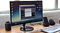
A Samsung Galaxy S8 plugged into a DeX docking station: The monitor is displaying the PowerPoint and Word Android applications.

USB-C devices

An increasing number of motherboards, notebooks, tablet computers, smartphones, hard disk drives, USB hubs and other devices released from 2014 onwards include the USB-C sockets. However, the initial adoption of USB-C was limited by the high cost of USB-C cables and the wide use of Micro-USB chargers.

Video output

Currently, DisplayPort is the most widely implemented alternate mode, and is used to provide video output on devices that do not have standard-size DisplayPort or HDMI ports, such as smartphones and laptops. All Chromebooks with a USB-C port are required to support DisplayPort alternate mode in Google's hardware requirements for manufacturers. A USB-C multiport adapter converts the device's native video stream to DisplayPort/HDMI/VGA, allowing it to be displayed on an external display, such as a television set or computer monitor.

It is also used on USB-C docks designed to connect a device to a power source, external display, USB hub, and optional extra (such as a network port) with a single cable. These functions are sometimes implemented directly into the display instead of a separate dock, meaning a user connects their device to the display via USB-C with no other connections required.

Compatibility issues

Power issues with cables

Many cables claiming to support USB-C are actually not compliant to the standard. Using these cables would have a potential consequence of damaging devices that they are connected to. There are reported cases of laptops being destroyed due to the use of non-compliant cables.

Some non-compliant cables with a USB-C connector on one end and a legacy USB-A plug or Micro-B receptacle on the other end incorrectly terminate the Configuration Channel (CC) with a 10 kΩ pullup to VBUS instead of the specification mandated 56 kΩ pullup, causing a device connected to the cable to incorrectly determine the amount of power it is permitted to draw from the cable. Cables with this issue may not work properly with certain products, including Apple and Google products, and may even damage power sources such as chargers, hubs, or PC USB ports.

When a defective USB-C cable or power source is used, the voltage seen by a USB-C device can be different from the voltage expected by the device. This may result in an overvoltage on the VBUS pin. Also due to the fine pitch of the USB-C receptacle, the VBUS pin from the cable may contact with the CC pin of the USB-C receptacle resulting in a short-to-VBUS electrical issue due to the fact that the VBUS pin is rated up to 20 V while the CC pins are rated up to 5.5 V. To overcome these issues, USB Type-C port protection must be used between USB-C connector and USB-C Power Delivery controller.

Compatibility with audio adapters

On devices that have omitted the 3.5 mm audio jack, the USB-C port can be used to connect wired accessories such as headphones.

There are primarily two types of USB-C adapters (active adapters with DACs, passive adapters without DACs) and two modes of audio output from devices (phones without onboard DACs that send out digital audio, phones with onboard DACs that send out analog audio).

When an active set of USB-C headphones or adapter is used, digital audio is sent through the USB-C port. The conversion by the DAC and amplifier is done inside of the headphones or adapter, instead of on the phone. The sound quality is dependent on the headphones/adapter's DAC. Active adapters with a built-in DAC have near-universal support for devices that output digital and analog audio, adhering to the Audio Device Class 3.0 and Audio Adapter Accessory Mode specifications.

Examples of such active adapters include external USB sound cards and DACs that do not require special drivers, and USB-C to 3.5 mm headphone jack adapters by Apple, Google, Essential, Razer, HTC, and Samsung.

On the other hand, when a passive set of USB-C headphones or adapter is used, analog audio is sent through the USB-C port. The conversion by the DAC and amplifier is done on the phone; the headphones or adapter simply passthrough the signal. The sound quality is dependent on the phone's onboard DAC. Passive adapters without a built-in DAC are only compatible with devices that output analog audio, adhering to the Audio Adapter Accessory Mode specification.

USB-C to 3.5 mm audio adapters and USB sound cards compatibility
Output mode Specification Devices USB-C adapters
Active, with DACs Passive, without DACs
Digital audio Audio Device Class 3.0 (digital audio) Google Pixel 2, HTC U11, Essential Phone, Razer Phone,
Samsung Galaxy Note 10, Samsung Galaxy S10 Lite, Sharp Aquos S2, Asus ZenFone 3, Bluedio T4S, Lenovo Tab 4, GoPro, MacBook etc.
Conversion by adapter Conversion unavailable
Analog audio
  • Audio Device Class 3.0 (digital audio)
  • Audio Adapter Accessory Mode (analog audio)
Moto Z/Z Force, Moto Z2/Z2 Force/Z2 Play, Moto Z3/Z3 Play, Sony Xperia XZ2, Huawei Mate 10 Pro, Huawei P20/P20 Pro, Honor Magic2, LeEco,
Xiaomi phones, OnePlus 6T, OnePlus 7/7 Pro/7T/7T Pro,
Oppo Find X/Oppo R17/R17 Pro, ZTE Nubia Z17/Z18 etc.
Conversion by adapter Passthrough

Compatibility with other fast charging technology

In 2016, Benson Leung, an engineer at Google, pointed out that Quick Charge 2.0 and 3.0 technologies developed by Qualcomm are not compatible with the USB-C standard. Qualcomm responded that it is possible to make fast charge solutions fit the voltage demands of USB-C and that there are no reports of problems; however, it did not address the standard compliance issue at that time. Later in the year, Qualcomm released Quick Charge 4 technology, which it cited to be – as an advancement over previous generations – "USB Type-C and USB PD compliant".

Regulations for compatibility

In 2021, the European Commission, proposed the use of USB-C as a universal charger. On 4 October 2022, the European Parliament voted in favor of the new law, Radio Equipment Directive 2021/0291, with 602 votes in favor, 13 against and 8 absentions. The regulation requires that all mobile phones, tablets, and cameras sold in the European Union would have to be equipped with a USB-C port by the end of 2024. These regulations will extend to laptops by spring 2026.

See also

Kids robot.svg In Spanish: USB-C para niños

  • USB hardware § Host and device interface receptacles
  • Thunderbolt (interface)
  • HDMI Version 2.1
kids search engine
USB-C Facts for Kids. Kiddle Encyclopedia.