
USB facts for kids
The Universal Serial Bus (USB) is a cool technology that lets you connect electronic devices to your computer. Think of it like a special cable and port that helps different gadgets talk to each other quickly. It's a fast way for computers and devices to share information.
You'll find USB on almost all personal computers, but also on other devices like smartphones and video game consoles. It's a standard way to connect many different things.
Most people use USB for their computer mice, keyboards, scanners, printers, digital cameras, and USB flash drives. There are billions of USB devices used all over the world!
USB was made to make devices "plug and play." This means you can plug a device into a free USB port, and it usually just works! Your computer will notice the new device. Sometimes, it might install a little bit of special software to help it work. You can also unplug the device when you're done using it, even while the computer is on. This is called "hot swapping." It means you don't have to turn off your computer to connect or disconnect USB devices.
USB can also give a small amount of power to the device through the USB cable. Devices that don't need much power can get it from the USB port. This means they don't need a separate power plug. This is why you see cool gadgets like USB battery chargers, lights, and small fans that just plug into a USB port.
Since 2015, USB has mostly taken the place of older ways to connect devices. These include the parallel port, serial port, and SCSI. These older ways are still used for a few special jobs where USB isn't quite right.
Contents
The Story of USB

The very first version of USB was created in 1995. It quickly became very popular! People who make electronic devices immediately saw how useful it would be. Today, USB connects computers, laptops, and MP3 players to many different devices.
Seven big technology companies worked together to create USB. These were Compaq, IBM, Intel, Microsoft, NEC, Northern Telecom, and Digital Equipment Corporation (DEC).
Years ago, before USB was released, many companies met at a special hotel in California. They called this meeting "Plugfest." They wanted to test their new USB devices. The meeting lasted three days. About 50 companies connected their USB devices to one main computer system to make sure everything worked together.
Even the USB logo has its own history! It took several months to design.
Here's a quick timeline of USB:
- 1994: Seven companies started working on USB.
- 1995: 340 companies joined the USB Implementation Forum to help develop USB.
- 1996: Over 500 USB products were being developed around the world.
- 1997: 60 more companies joined the USB Implementation Forum.
- 1998: USB became super popular in electronics.
- 2000: USB 2.0 was introduced. This is still one of the most common USB types today.
- 2005: USB became wireless!
- 2008: USB 3.0 was introduced. It's more than 10 times faster than USB 2.0.
- 2013: USB 3.1 was introduced. It's about twice as fast as USB 3.0.
- 2015: USB Type-C was introduced. This is a cool new connector because you can plug it in either way – there's no "wrong" way!
USB Speeds and Types
Currently, there are five main USB standards: USB 1.0, USB 1.1, USB 2.0, USB 3.0, and USB 3.1. USB 3.1 came out in 2016 and made USB 3.0 even faster. It often uses a new connector called USB Type-C, which you can plug in either way. USB 1.0 is very rarely used now.
USB offers different speeds for transferring data:
- Low speed: 1.5 million bits per second (MBit/s)
- Full Speed: 12 MBit/s
- Hi Speed: 480 MBit/s (available in USB 2.0 and newer)
- Super Speed: 5 billion bits per second (Gbit/s) (available in USB 3.0 and newer)
- Super Speed+: 10 Gbit/s
These speeds are the raw bit rates. The actual speed you get might be a bit lower because of how the data is sent.
For a device to use the Hi Speed or Super Speed rates, both the USB port on your computer and the device itself need to support that speed. USB is backward compatible. This means you can connect a newer, faster USB device to an older, slower USB port, or vice versa. They will just work at the slower speed.
USB Hubs for More Ports

Most computers today have USB ports, usually supporting USB 2.0 or newer. However, the number of ports is often limited, usually between two and six. USB lets you connect USB hubs to add even more USB ports.
The hubs themselves also follow a USB standard. If you connect devices to a USB 1.1 hub, they will only work at USB 1.1 speeds. But if you connect devices to a newer hub, they can use faster speeds if they support them.
USB Connectors: Easy to Use


USB was designed to be super easy to use. Engineers learned from older connectors when they designed USB. There are three main types of USB connectors:
- Type A: This is the most common end you see that plugs into your computer.
- Micro-A (rarely used)
- Type B: This end usually plugs into the device, like a printer.
- Micro-B: This is common for most smartphones and small devices.
- Type C: This is a newer type that can plug into either the computer or the device. Many new computers, phones, and accessories use it.
How Easy Are They to Use?
- With USB Type A and B connectors, you can't plug them in the wrong way. They only fit one way up. You can usually tell by looking or feeling how it goes in. Sometimes, you might need to try both ways if you can't see clearly.
- Type C USB connectors are even easier! You can plug them in either way, upside down or right side up. It doesn't matter!
- You don't need to push or pull very hard to plug in or unplug a USB cable. This was part of the design. USB cables and small devices stay in place just by the grip of the port. They don't need screws or clips. This makes it easy to connect devices even in tricky spots or for people who have trouble with their hands.
- Before Type C, the connectors made sure you connected devices in the right order. USB doesn't work in a circle, so the connectors were designed to prevent that.

How Strong Are They?
- USB connectors are built to be tough. Older connector designs were often fragile, with parts that could easily bend or break. But USB connectors have their electrical parts protected by a plastic piece. The whole connector is usually inside a metal cover. This means you can handle, plug in, and unplug USB connectors safely, even if you're not super careful.
- The way USB connectors are built helps protect your devices. The metal outside of the plug touches the port first. This metal part is usually connected to the computer's ground, which helps safely get rid of any static electricity. This protects the delicate electronic parts inside. It also helps shield the USB signal from interference. Also, the power connections are made before the data connections. This allows you to safely plug and unplug devices while they are on (hot-swapping).
- The newer USB Micro-B ports are designed to be plugged in and unplugged up to 10,000 times! This is much more than the 500 times for standard USB and Mini-USB. They did this by moving the part that wears out the most to the cable side. This way, if something wears out, it's the cable (which is cheaper to replace) instead of the device itself.
How Well Do They Work Together?
- The USB standard allows for some differences in how connectors are made. This helps make sure that USB connectors from different companies still work well together. Unlike many other connectors, the USB rules also say how big a device can be around its plug. This stops a device from being so big that it blocks other nearby USB ports.
- USB allows for two-way communication. Usually, cables have plugs, and computers and devices have ports. Type-A plugs only fit Type-A ports, and Type-B plugs only fit Type-B ports. However, a special feature called USB On-The-Go lets a single port act as either a computer (host) or a device. This is useful for things like PDAs that might connect to a PC as a device, but then connect to a keyboard as a host.
How USB Works Inside
A USB system has a special design. It has a main host (your computer), several USB ports, and many devices connected to it. It's like a tree structure, with the computer at the root and devices branching off. You can even add more USB hubs to create more branches, up to five levels deep.
Your computer can have several USB controllers. Each controller provides one or more USB ports. You can connect up to 127 devices, including hubs, to a single controller.
USB devices are linked together through hubs. There's always one main hub called the "root hub," which is built into your computer's USB controller. There are also special "sharing hubs" that let multiple computers use the same devices. They switch access between the computers, either manually or automatically. These are popular in small offices.
A physical USB device can have several different parts that do different jobs. For example, a webcam might have a video part (for the camera) and an audio part (for the microphone).
.svg)
USB devices talk to each other using "pipes." These are like logical channels that connect your computer's controller to a specific part of the device called an "endpoint." A USB device can have up to 32 active pipes, 16 sending data to the computer and 16 sending data from the computer.
Each endpoint can only send data in one direction. Endpoints are grouped into "interfaces," and each interface is linked to a specific job the device does. There's one special endpoint, endpoint zero, which is used for setting up the device and isn't linked to any specific job.
When you first plug a USB device into your computer, a process called "enumeration" starts. The computer sends a signal to the device. It figures out how fast the device can work. Then, the computer reads information from the device and gives it a unique address. If your computer supports the device, it loads the necessary software (drivers) to make it work. If you restart your computer, this process happens again for all connected devices.
Your computer's USB controller constantly checks the USB connection for activity. No USB device can send data without your computer's controller asking it to.
USB Device Categories
USB devices are put into different categories, called "device classes." This helps your computer know what kind of device it is and how to talk to it. Your computer's operating system usually has general software (drivers) for these common classes, so many USB devices just work when you plug them in.
Here are some common USB device classes:
| Class | What it's for | Examples |
|---|---|---|
| Audio | Sound devices | Speakers, microphones, sound cards |
| Communications | Devices that help with communication | Ethernet adapters, modems, serial port adapters |
| Human Interface Device (HID) | Devices you use to control your computer | Keyboards, mice, joysticks |
| Image | Cameras and imaging devices | Digital cameras (many cameras also act like storage devices) |
| Printer | Printers | Laser printers, Inkjet printers |
| Mass Storage | Devices that store data | USB flash drives, memory card readers, external hard drives |
| USB hub | Devices that add more USB ports | Full speed hubs, hi-speed hubs |
| Smart Card | Smart card readers | USB smart card readers |
| Video | Video devices | Webcams |
| Wireless Controller | Wireless devices | Wi-Fi adapter, Bluetooth adapter |
| Vendor Specific | Devices that need special software from their maker | (These devices need drivers specifically from the company that made them.) |
Related pages
Images for kids
-
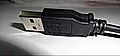
The USB logo on a common Type A plug.
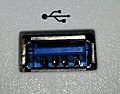
-
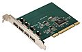
A USB 2.0 PCI expansion card for adding USB ports to an older computer.
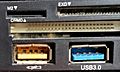
-
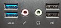
Two USB 3.0 ports (left) and two USB 2.0 ports (right) on a computer's front.
-
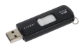
A flash drive, a common USB storage device.
-
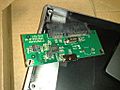
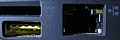
The circuit board from a USB 3.0 external hard drive case.
-
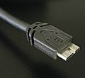
A USB 3.0 Micro-B SuperSpeed plug.
-
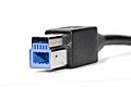
A USB 3.0 B type plug.
-
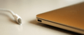
A USB-C port on an Apple MacBook.
-
An orange USB port, often used for charging.
-
A blue Standard-A USB connector on a modem router.
-
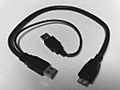
A Y-shaped USB 3.0 cable, which can draw power from two USB ports.
-
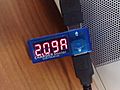
A small device that shows the voltage and current for devices charged over USB.
-
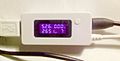
This USB power meter also shows the charge (in mAh) and can record data.
-
A yellow USB port that can charge devices even when the computer is asleep.
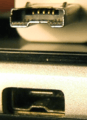
-
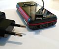
The Micro-USB port is often found on mobile phone chargers.
-
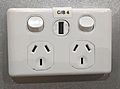
A wall power socket with a built-in USB charger port.
-
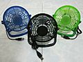
Small fans powered by USB.
-
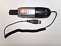
A fun USB vacuum cleaner novelty device.
-

Many different USB cables for sale in Hong Kong.
-
An HTC ExtMicro USB port and connector.
-
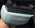
A Nokia Pop-Port connector.
-
An Apple Lightning-to-USB adapter and cable.


.jpg)


_meter_2.jpg)


See also
 In Spanish: Universal Serial Bus para niños
