
Caisson lock facts for kids
A caisson lock is a special type of canal lock. Imagine a giant, sealed box that can float. This box is called a "caisson." Instead of using many regular locks, a caisson lock lifts or lowers a narrowboat between two different water levels in one go.
It was invented in the late 1700s to solve a big problem: regular locks use a lot of water, especially when boats need to go up or down a long way. Caisson locks were designed to save water and cost less to build than many traditional locks. They could replace up to seven normal locks and were much faster. However, the technology back then wasn't quite ready to build them easily or cheaply.
Contents
How Caisson Locks Were Invented
The idea for the caisson lock came from Robert Weldon. He first showed off a smaller version of his invention in 1792 at Oakengates, on a part of the Shropshire Canal that no longer exists.
Weldon believed his design would help canals save water, especially during dry times or in high places. He also thought it would be cheaper than building long aqueducts or tunnels. Plus, it would be much quicker for boats to pass through than many regular locks. He called his invention the 'Hydrostatick Caisson Lock'.
Building the First Big Caisson Lock
The owners of the Kennet and Avon Canal were very interested in Weldon's idea. A new coal mining area in Somerset needed a way to transport coal, and a canal was planned to connect to the Kennet and Avon. But this new canal, the Somerset Coal Canal, had big problems with water supply at a place called Combe Hay.
So, the Kennet and Avon Company suggested Weldon's caisson locks as the answer. They planned to build three of them. The first one was finished in 1797, with Weldon helping to build it. Even though it was shown to the Prince Regent (who later became King George IV), it had many engineering problems. These issues might have been caused by the soft ground in the area.
How a Caisson Lock Works
The caisson lock used a large, sealed box (the "caisson") that stayed underwater. This box was made heavy enough so it would float evenly, like a submarine. It couldn't just float up to the surface for a boat to enter.
Instead, a stone chamber, like a big pool, was built. This chamber was always full of water, even when the caisson was at its highest point. A large door sealed the lock chamber from the canal above.
Moving Boats Up and Down
To lower a boat:
- The caisson box was first pulled up to its highest position using a special gear system.
- Then, the outer door was lifted up.
- Water levels inside the box and the canal were made equal.
- The inner door of the caisson opened, and the boat floated in.
- Once the boat was inside, the doors closed.
- The caisson was then slowly lowered. Because the boat floating in replaced its own weight of water, the total weight of the box stayed the same. This meant it didn't take a huge effort to move it.
- At the bottom, the process was reversed to let the boat out.
The amazing thing was that almost no water was lost during this whole process, except for tiny leaks!
Caisson Locks Compared to Boat Lifts
The caisson lock is a bit like a boat lift, but it works underwater. Both were developed around the same time. Each had its own good and bad points for the engineers of that era.
One challenge with caisson locks was making sure the submerged box was perfectly sealed and safe, especially if people stayed inside.
However, caisson locks could be moved just by changing their buoyancy. By pumping a little water in or out of the caisson, it could float up or down. A boat lift, on the other hand, needed a strong mechanical system to lift the entire weight of the caisson and its water. Back then, steam engines were new and mostly used for pumping water, not for providing strong lifting power. So, moving a caisson by buoyancy was often more practical.
Dimensions of the Built Lock
The caisson lock at Combe Hay had these approximate measurements:
- Height: 66 feet (20 meters)
- Width: 10 to 20 feet (3 to 6 meters)
- Length: 88 feet (27 meters)
- The toothed rack (for moving it): 46 feet (14 meters)
- Time for one rotation (up or down): about 7 minutes
Tests and Problems
Several tests were done on the first caisson lock:
- February 1798: Cracks appeared.
- June 1798: Successful test.
- April 1799: Three successful tests. One test even carried 60 passengers!
- May 1799: The box got stuck because of a stone sticking out.
During the May 1799 test, some investors were on board the boat and almost couldn't breathe before they were freed. Because of this scary incident, work on the second lock stopped. Instead, an inclined plane was built, which used wheeled carts to move boat cargo up the slope. Later, a series of nineteen regular locks were built, along with a powerful steam pumping station to reuse the water.
Other Caisson Lock Ideas
In 1815, the Regents Canal Company in London tried to build a different kind of caisson lock. It was designed by William Congreve. This lock also aimed to save water and speed up boat passage.
Congreve's design used two caissons that were always underwater and moved up and down by balancing air pressure between them. He thought one person could operate it in three minutes using an air compressor. However, it actually took six minutes, and the effort was too much for the operator. Also, the caissons leaked air, which was a big problem. After many failed attempts to fix them, the company switched to regular locks in 1818.
Another inventor, Jonathan Brownill, patented a similar idea in 1828. His design used three caissons and a system of wedges to seal the main caisson.
Even with these different ideas, no caisson lock has ever been built and used successfully for a long time.
Images for kids
-
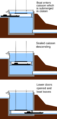
How a caisson lock works
-
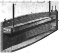
An old picture of the lock at Combe Hay


