
Space Shuttle Solid Rocket Booster facts for kids

Two Space Shuttle SRBs on the crawler-transporter
|
|
| Manufacturer | Thiokol, later ATK United Space Boosters Inc., Pratt and Whitney |
|---|---|
| Country of origin | United States |
| Used on | Space Shuttle |
| General characteristics | |
| Height | 149.16 ft (45.46 m) |
| Diameter | 12.17 ft (3.71 m) |
| Gross mass | 1,300,000 lb (590 t) |
| Propellant mass | 1,100,000 lb (500 t) |
| Empty mass | 200,000 lb (91 t) |
| 4-segment SRB | |
| Motor | 1 |
| Thrust | 3,300,000 lbf (15,000 kN) sea level |
| Specific impulse | 242 seconds (2.37 km/s) |
| Burn time | 127 s |
| Fuel | PBAN-APCP |
The Space Shuttle Solid Rocket Booster (SRB) was a very powerful rocket used to launch the Space Shuttle into space. A pair of these boosters provided most of the power (85%) needed for the Shuttle to lift off. They worked for the first two minutes of the flight. After their fuel ran out, they separated from the Shuttle. Then, they parachuted down into the Atlantic Ocean. Special ships would pick them up. After being checked and fixed, these boosters could be used again for future missions.
The Space Shuttle SRBs were the strongest solid rockets ever used to launch people. Later, the Space Launch System (SLS) SRBs, which were based on the Shuttle's design, became even more powerful. This happened after the Artemis-1 mission launched in 2022. Each Space Shuttle SRB produced a huge amount of thrust, about 14.7 MN (3,300,000 lbf). This was roughly twice the power of the strongest liquid-fueled rocket engine at the time, the Rocketdyne F-1. Together, the two SRBs weighed about 1,180 t (1,160 long tons; 1,300 short tons). This was more than half the total weight of the Shuttle at liftoff! Companies like Thiokol (later ATK) and USBI (a part of Pratt and Whitney) built these boosters.
Out of 270 SRBs launched during the Space Shuttle program, almost all of them (all but four) were recovered. This allowed engineers to check them after flights. They could find any problems and make the boosters better. For example, the SRBs used for the very last Shuttle mission, STS-135, had parts that had flown on 59 previous missions.
Contents
How the SRBs Worked


The two reusable SRBs gave the main push to lift the Space Shuttle off the launch pad. They helped it reach an altitude of about 150,000 ft (28 mi; 46 km). While the Shuttle was on the launch pad, the SRBs supported the entire weight of the external fuel tank and the orbiter. Each booster created about 2,800,000 pounds-force (12 MN) of thrust at sea level. This power increased to about 3,300,000 lbf (15 MN) shortly after liftoff.
The SRBs were lit only after the Shuttle's three main engines (called RS-25s) were confirmed to be working correctly. About 75 seconds after the SRBs separated, they reached their highest point, around 220,000 ft (42 mi; 67 km). Then, parachutes opened, and they landed in the ocean about 122 nautical miles (226 km) away. The SRBs helped the Space Shuttle reach a height of 28 miles (45 km) and a speed of 3,094 mph (4,979 km/h).
Once the SRBs ignited, the Shuttle was committed to launch. There was no way to stop the launch until both boosters had used all their fuel and were safely jettisoned. If an SRB had a major problem with its thrust, it would likely not have been a survivable event.
The SRBs were the largest solid-propellant motors ever flown and the first of their kind designed to be reused. Each one was 149.16 ft (45.46 m) long and 12.17 ft (3.71 m) wide. At launch, each SRB weighed about 1,300,000 lb (590 t). Together, they made up about 69% of the Shuttle's total weight at liftoff.
The main fuel for the SRBs was ammonium perchlorate (an oxidizer) and aluminum powder (the fuel). Each motor held about 1,100,000 lb (500 t) of this fuel. The empty weight of each SRB was about 200,000 pounds (91 t).
Each booster had several key parts. These included the motor itself (with its casing, fuel, igniter, and nozzle), structural parts, and systems for separation, recovery, and steering.
It's important to know the difference between "solid rocket motor" and "solid rocket booster." The "solid rocket motor" refers to the part that holds the fuel and creates thrust. The "solid rocket booster" is the complete rocket assembly. This includes the motor, plus parachutes, electronics, small separation rockets, and steering systems.
Each booster was connected to the external fuel tank at its back by two braces and a diagonal attachment. The front of each SRB was also connected to the external tank. On the launch pad, the boosters were held down by four special bolts. These bolts broke apart at liftoff.
The boosters were made of seven steel sections. These sections were put together in pairs by the manufacturer. Then, they were shipped to Kennedy Space Center for final assembly. The sections were joined using special pins and sealed with O-rings and heat-resistant putty. After the Challenger disaster in 1986, the design was improved to use three O-rings instead of two.
Parts of the SRB

Hold-Down Posts: Keeping the Shuttle in Place
Each SRB had four posts that fit into the launch platform. Special bolts held the SRB and platform together. These bolts had a frangible nut at the top. This nut contained two small explosive devices called NASA Standard Detonators (NSDs). When the SRB was ignited, these NSDs fired.
When the NSDs fired, the bolts were released and moved downward into a sand-filled container. This allowed the Shuttle to lift off. The bolts were about 28 in (710 mm) long and 3.5 in (89 mm) wide.
The commands to ignite the SRBs came from the Shuttle's computers. These commands also told the hold-down NSDs to fire. The launch system checked the voltage of these firing devices. If the voltage was too low in the last 16 seconds before launch, the launch would be stopped.
Electrical Power: Keeping Systems Running
Each SRB received electrical power from the orbiter. This power was sent through three main lines, or buses, labeled A, B, and C. If one of the orbiter's main power lines failed, the other lines could provide backup power. This setup made sure that all SRB systems stayed powered.
The normal operating voltage for these systems was about 28 volts DC.
Hydraulic Power Units: Moving the Nozzle
Each SRB had two separate Hydraulic Power Units (HPUs). Each HPU included an auxiliary power unit (APU), a fuel supply, a hydraulic pump, and a hydraulic fluid system. The APUs used hydrazine fuel to create mechanical power. This power drove a hydraulic pump, which created pressure for the SRB's hydraulic system.
These two HPUs were located at the back of each SRB, near the nozzle. They started working 28 seconds before liftoff and stopped when the SRBs separated. The two hydraulic systems were connected to the parts that moved the SRB nozzle.
The HPUs and their fuel systems were kept separate from each other. Each fuel tank held about 22 lb (10.0 kg) of hydrazine. This fuel was pushed out by pressurized nitrogen gas.
The APU worked by breaking down hydrazine into hot, high-pressure gas. This gas spun a turbine, which created mechanical power. This power then drove the fuel pump and the hydraulic pump. Each HPU could provide enough hydraulic power for both nozzle-moving parts, even if the other HPU had a problem.
The HPUs and their hydraulic systems were designed to be reused for up to 20 missions.
Thrust Vector Control: Steering the Rocket
Each SRB had two hydraulic parts called servoactuators. These parts moved the nozzle up, down, and side-to-side. This movement, called thrust vectoring, helped control the Shuttle's direction (roll, pitch, and yaw) during liftoff and ascent.
The Shuttle's flight control system sent commands to these servoactuators. This system made sure the thrust from the main engines and SRB nozzles worked together to steer the Shuttle. Four independent control channels sent signals to the SRB servoactuators.
Each servoactuator had four independent valves that received signals. These valves worked together to position the actuator and the nozzle, controlling the direction of thrust. If one input was wrong, the system could ignore it.
Sensors on each actuator sent information back to the control system about the nozzle's position. Inside each servoactuator was a special part that cushioned the nozzle when it hit the water during splashdown. This prevented damage to the nozzle.
Rate Gyro Assemblies: Knowing the Shuttle's Position
Each SRB had three rate gyro assemblies (RGAs). Each RGA contained gyros that measured how fast the Shuttle was rotating around its pitch and yaw axes. This information was sent to the orbiter's computers. It helped the guidance and control system steer the Shuttle during the first part of the flight. After the SRBs separated, the Shuttle switched to its own gyros.
The RGA information was sent to the orbiter's main computers. The system would pick the middle value from the three RGAs to get accurate pitch and yaw rates. These RGAs were designed to last for 20 missions.
Segment Cases: The Strong Outer Shell
The SRB segments were made from a very strong steel, about 2 centimeters (0.8 inches) thick.
Propellant: The Rocket Fuel

The rocket fuel inside each solid rocket motor was a mix of several ingredients. It was mostly ammonium perchlorate (an oxidizer, 69.6% by weight) and aluminum powder (the fuel, 16%). It also contained a small amount of iron oxide (a catalyst, 0.4%), PBAN (a binder that also acts as fuel, 12.04%), and an epoxy curing agent (1.96%). This type of fuel is called ammonium perchlorate composite propellant (APCP).
This fuel gave the motors a good specific impulse (a measure of efficiency) of 242 seconds (2.37 km/s) at sea level. When ignited, the motor burned the fuel at a high pressure of about 906.8 psi (6.252 MPa).
Aluminum was chosen as a fuel because it packs a lot of energy into a small space and is resistant to accidental ignition.
The fuel inside the motor was shaped in a special way. The front section had an 11-pointed star shape. The back sections had a double-truncated-cone shape. This design made the rocket produce a lot of thrust at the start of the flight. Then, it reduced the thrust by about one-third after 50 seconds. This was done to prevent too much stress on the Shuttle when it reached maximum dynamic pressure.
How the SRBs Functioned
Ignition: The Moment of Liftoff
SRB ignition could only happen after a safety pin was removed by the ground crew. At T-5 minutes (5 minutes before launch), a device on the SRB was set to "arm." The solid rocket motors were ignited only when the Shuttle's three main engines reached 90% of their power. Also, there had to be no problems with the main engines or the SRB ignition system.
The commands to ignite the SRBs came from the orbiter's computers. These commands went to the special detonators (NSDs) in each SRB. A special device called a PIC controlled the firing of each explosive. Three signals had to be present at the same time for the PIC to work. These signals came from the orbiter's computers.
The launch sequence also controlled important valves in the main engine system. It checked if the main engines were ready. The main engines started at T-6.6 seconds (they started one after another very quickly). All three main engines had to reach 90% thrust within three seconds. If not, the launch would be stopped.
If the main engines reached 90% thrust normally, they would be set to 100% power at T-3 seconds. At this time, the "fire 1" command was sent to arm the SRBs. At T-3 seconds, the Shuttle stack would also "twang" or bend slightly. This movement was about 25.5 in (650 mm) at the top of the external tank.
The "fire 2" commands caused the detonators to fire. This ignited a small booster charge, which then ignited the main fuel in the SRB. The fuel burned along its entire surface almost instantly.
At T-0 (liftoff), the two SRBs ignited. The four explosive bolts holding each SRB to the launch pad broke apart. The two cables connecting the Shuttle to the ground were pulled away. The Shuttle's timers started, and the three main engines were at 100% power. The ground launch sequence ended.
Lift-off and Ascent: Soaring Skyward
Precise timing during ignition was vital for a successful liftoff. The explosive hold-down bolts helped manage the forces created by the main engines starting up. Without these bolts, the main engines would have tipped the Shuttle stack over. When the SRBs reached full thrust, the bolts exploded, releasing the Shuttle. At this moment, the forces were balanced, and the Shuttle began to rise vertically. The Shuttle's computers controlled the movements of the main engine and SRB nozzles to steer the vehicle.
During the climb into space, sensors detected the Shuttle's flight and position. The flight computers translated steering commands into movements for the engine and motor nozzles. This kept the Shuttle on its correct path. As the Shuttle used fuel, gained speed, and faced different air resistance, it automatically adjusted its direction.
Separation: Boosters Break Away
The SRBs separated from the Space Shuttle at an altitude of about 146,000 feet (45 km). This happened when the pressure inside both SRB motors dropped to a certain level (less than or equal to 50 psi (340 kPa)). There was also a backup timer in case the pressure sensors failed. When separation began, the thrust steering actuators moved to a neutral position. This made sure the thrust from each SRB was less than 100,000 lbf (440 kN).
The SRBs separated from the external tank very quickly, within 30 milliseconds of the command. The front connection point was a ball-and-socket joint held by one bolt. This bolt also carried wires for the range safety system. The back connection points had three struts. Each strut had a bolt with explosive charges.
There were four small booster separation motors (BSMs) on each end of each SRB. These BSMs pushed the SRBs away from the external tank. They ignited when the separation commands were sent from the orbiter.
Range Safety System: Keeping People Safe
A range safety system (RSS) is designed to destroy a rocket if it goes off course. This prevents danger to people on the ground from falling pieces or explosions. The Shuttle's RSS was only used once, during the Space Shuttle Challenger disaster. It was activated 37 seconds after the vehicle broke apart, when the SRBs were flying out of control.
The Shuttle had two RSS, one in each SRB. Both could receive two commands from the ground: "arm" and "fire." The RSS was only used if the Shuttle flew outside its safe path.
The RSS included antennas, receivers, decoders, and explosive devices. The "arm" command allowed the system to be ready for destruction. The "fire" command caused the explosives to ignite, destroying the booster.
The RSS systems in both SRBs were connected. So, if one SRB received a command, the other would too. The RSS was powered by batteries in each SRB.
Descent and Recovery: Bringing Them Home

The SRBs were jettisoned from the Shuttle system at 2 minutes into flight, at an altitude of about 146,000 feet (45 km). After rising to about 220,000 feet (67 km), they began to fall back to Earth. Once they re-entered the thicker atmosphere, a parachute system slowed them down. This prevented damage when they hit the ocean. A command was sent from the orbiter to the SRB just before separation to start the recovery system.
The recovery process began when a high-altitude sensor detected the correct height. This triggered small thrusters that ejected the nose cap. The nose cap separation happened at about 15,704 ft (4,787 m). This deployed a small pilot parachute, which then pulled out a larger drogue parachute. The drogue parachute was 54 ft (16 m) wide and helped stabilize the SRB. It opened in stages to slow the booster down. The drogue parachute weighed about 1,200 lb (540 kg).
.jpg)
After the drogue chute stabilized the SRB, the frustum (a cone-shaped part) separated from the booster. This happened at about 5,500 ft (1,700 m). The frustum was pulled away by the drogue chute, which then pulled out the three main parachutes. These main parachutes were 136 ft (41 m) wide and also opened in stages. They slowed the SRB to a safe speed for water impact. Each main parachute weighed about 2,180 lb (990 kg). These were the largest parachutes ever used for their size and the weight they carried.
The SRB hit the water about 279 seconds after separation, at a speed of about 76 feet per second (23 m/s). They landed about 130 nmi (240 km) off the coast of Florida. Because the parachutes made the nozzle hit the water first, air was trapped inside the empty motor casing. This made the booster float with its front end sticking about 30 feet (9 m) out of the water.

Special NASA recovery ships, the MV Freedom Star and the MV Liberty Star, recovered the SRBs and their parachute systems. Once a booster was found, divers would plug its nozzle. They would then pump air into the booster and water out of it. This made the SRB float horizontally, which was easier for towing. The recovery ships then towed the boosters and other recovered parts back to Kennedy Space Center.
The Challenger Disaster and SRB Improvements

The tragic loss of Space Shuttle Challenger in 1986 was caused by a problem with one of its SRBs. An investigation found that the design of the SRB joints was faulty. It was also made worse by the unusually cold weather on the morning of the launch. The rubber O-ring seals in the joints did not work well in cold temperatures. This allowed hot exhaust gases to escape from the right SRB during launch. This leak burned a hole in the nearby external fuel tank and weakened a support strut. The SRB then partially detached, hitting the external tank. This led to the destruction of the external tank and the disintegration of Challenger. Both SRBs actually survived the accident. Before the disaster, engineers had warned against launching in the cold weather, but their concerns were not followed.
After the Challenger disaster, engineers carefully studied the SRB's structure. They focused on areas where problems had been seen after previous flights.
One area was the attachment ring that connected the SRBs to the external tank. They noticed stress in some of the fasteners where the ring attached to the motor case. This was due to the high forces during water impact. To fix this, the attachment ring was redesigned to go all the way around the motor case (360 degrees). Before, it only went around 270 degrees.

Also, special tests were done on the aft skirt (the bottom part of the SRB). During one test, a problem was found in a critical weld. The design was changed to add stronger support brackets in the aft ring of the skirt.
These two changes added about 450 lb (200 kg) to the weight of each SRB. The improved version was called the Redesigned Solid Rocket Motor (RSRM).
Building and Transporting SRBs
The main company that made the SRB motor segments was ATK Launch Systems (formerly Morton Thiokol Inc.) in Magna, Utah.
United Space Boosters Inc. (USBI) was the main contractor for putting the SRBs together, checking them, and fixing them after flights. They also handled the recovery of the spent SRBs. USBI was later absorbed by United Space Alliance.
Parts of the SRBs were shipped from Utah to the Kennedy Space Center in Florida by train. This journey took 12 days and covered 2,000 miles (3,200 km) across eight states. Each segment and its special rail car weighed about 300,000 pounds (140,000 kg). Empty cars were placed between the SRB cars to spread out the weight, especially over bridges. After being recovered, the used segments were loaded back onto the same train cars and sent back to Utah to be refurbished and refueled.
Train Incident
On May 2, 2007, a freight train carrying SRB segments derailed in Myrtlewood, Alabama. A rail trestle collapsed. The train was carrying eight SRB segments for future Shuttle missions. Four segments fell about 10 feet (3.0 m). The other four segments and a car with nozzles remained on solid ground. The fallen segments were recovered and sent back to Utah for inspection. The segments that did not fall were found to be safe and continued their journey to Florida.
Future Uses of SRB Technology

Over the years, several ideas were proposed to reuse the SRB design. However, none of these plans led to regular flights before being canceled. Until the first flight of the Space Launch System (SLS) in 2022, only a test flight of the Ares I-X prototype in 2009 actually flew using a design based on the SRB.
Ares Rockets
NASA initially planned to use the four-segment SRB design for several Ares rockets. These rockets would have launched the Orion spacecraft. In 2005, NASA announced the Shuttle-Derived Launch Vehicle program. The Ares I rocket was planned to use a modified four-segment SRB for its first stage.
Later, the Ares I design was updated to use a five-segment SRB. This five-segment booster was originally developed for the Shuttle but never used. The Ares V was a heavy-lift rocket. Early designs of Ares V used five Space Shuttle Main Engines and two five-segment boosters.
The Constellation program, which included Ares I and Ares V, was canceled in 2010.
Space Launch System (SLS)
_(cropped).jpg)
Two Space Launch System SRBs launching Artemis 1 mission to space
|
|
| Manufacturer | Thiokol, later ATK United Space Boosters Inc., Pratt and Whitney, Northrop Grumman |
|---|---|
| Country of origin | United States |
| Used on | Space Launch System |
| General characteristics | |
| Height | 177 ft (54 m) |
| Diameter | 12.17 ft (3.71 m) |
| Gross mass | 1,600,000 lb (730 t) |
| Propellant mass | 1,400,000 lb (640 t) |
| Empty mass | 200,000 lb (91 t) |
| 5-segment SRB | |
| Motor | 1 |
| Thrust | 3,280,000 lbf (14,600 kN) sea level |
| Specific impulse | 269 seconds (2.64 km/s) |
| Burn time | 126 s |
| Fuel | PBAN-APCP |

The first versions of the Space Launch System (SLS) use a pair of five-segment Solid Rocket Boosters. These were developed from the four-segment SRBs used for the Shuttle. The SLS SRBs have an added center segment, new electronics, and lighter insulation. These five-segment SRBs provide about 25% more total power than the Shuttle SRBs. Unlike the Shuttle SRBs, they are not recovered after use.
SRBs on Display
You can see Space Shuttle Solid Rocket Boosters at several locations. These include the Kennedy Space Center Visitor Complex in Florida, the Stennis Space Center in Mississippi, and the United States Space & Rocket Center in Alabama. There are also displays at the March Field Air Museum in California and at Orbital ATK's facility near Promontory, Utah. A part of a filament-wound booster case is on display at the Pima Air & Space Museum in Tucson, Arizona.
Images for kids
-
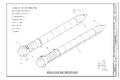
Labeled diagram of an SRB.
See also
 In Spanish: Cohetes Aceleradores Sólidos (transbordador espacial) para niños
- Solid rocket booster
- PEPCON disaster
- Studied Space Shuttle variations and derivatives
