
Electric power transmission facts for kids


Electric power transmission is how we move large amounts of electricity from where it's made to where people use it. Think of it as a superhighway for electricity! Power plants create electricity, and then it travels through special lines to substations near towns and cities. From these substations, smaller lines called distribution lines take the electricity right to your homes and schools.
To send electricity over long distances, it's usually sent at very high voltages (like 110,000 volts or more). This helps prevent a lot of energy from being lost along the way. Most of the time, electricity travels through big overhead power lines. But in busy cities, it can also go through underground cables.
Sometimes, people call the whole system of power transmission a "grid." This network is designed so that electricity can reach any area from different power plants, making sure you always have power.
Contents
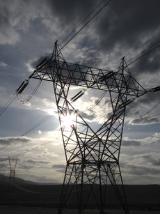
How Electricity Travels Overhead
_line.jpg)
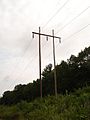
The wires used for high-voltage overhead lines don't have insulation around them. They are usually made of an aluminum alloy. Sometimes, steel strands are added inside for extra strength. Copper was used in the past, but aluminum is lighter and costs less.
These wires come in different sizes. Thicker wires can carry more electricity. When a lot of power needs to be sent, several parallel wires are used together. This is called a "bundle conductor." Using bundled wires also helps reduce energy loss from something called corona discharge.
Today, voltages of 110,000 volts and higher are considered "transmission-level." Lower voltages, like 66,000 or 33,000 volts, are sometimes used for shorter lines or lighter loads. Voltages below 33,000 volts are usually for local distribution. Very high voltages, above 765,000 volts, need special designs for the equipment.
Since overhead wires use air for insulation, they need to be a certain distance from the ground and other objects for safety. Bad weather, like strong winds, can sometimes cause problems. Winds can make the wires sway too much, leading to power outages.
Underground Transmission
Electricity can also travel through underground power cables. These cables take up less space and are hidden from view. They are also less affected by bad weather.
However, underground cables cost a lot more to install and maintain. If there's a problem with a buried line, it takes longer to find and fix it. Also, long underground cables can lose more power than overhead lines, especially for AC electricity. DC cables don't have this problem.
History of Power Transmission

In the early days of electricity, power could only be sent short distances. This was because it used direct current (DC), which was hard to change to a higher voltage for long trips. Different types of electrical devices needed different voltages. So, power generators had to be very close to where the electricity was used.
The idea of sending electricity using alternating current (AC) changed everything. In 1881, Lucien Gaulard and John Dixon Gibbs created an early transformer. This device could change the voltage of AC electricity.
The first long-distance AC line was built in Italy in 1884. It was 34 kilometers (about 21 miles) long. This showed that AC electricity could be sent over long distances. In 1885, the first working AC line for public lighting was set up in Rome, Italy.

An engineer named William Stanley, Jr. improved the transformer design in 1885. With support from George Westinghouse, he set up a demonstration system in Massachusetts in 1886. It sent 500 volts of electricity, which was then "stepped down" to 100 volts for lights in 23 businesses. This successful test led Westinghouse to start using AC systems.
In 1888, the first working AC motor designs appeared. These were induction motors that ran on polyphase current. This was a big step because it meant AC electricity could power machines, not just lights. Later, the three-phase system we use today was developed.
By the late 1800s and early 1900s, many smaller electric companies joined to form larger ones. They kept improving AC systems. Over time, AC became the main way to transmit power. Old DC systems were slowly replaced or connected to the AC grid using special devices.

The first long-distance transmission of single-phase AC happened in Oregon in 1890. Power traveled 14 miles from a hydroelectric plant to Portland. The first three-phase AC transmission took place in Germany in 1891. A 15,000-volt line connected two cities, about 175 kilometers (109 miles) apart.
Throughout the 20th century, the voltages used for power transmission kept increasing. By 1914, many systems were operating at over 70,000 volts. The highest was 150,000 volts.
Connecting many power plants over a large area helped reduce the cost of making electricity. It also made the power supply more reliable. If one plant had a problem, others could help. This also allowed using cheaper energy sources, like hydroelectric power, even if they were far away.
As industries grew in the 20th century, electric transmission lines became very important for most countries. The need for power during World War I led governments to build huge power plants. These plants were later connected to supply power to homes and businesses.
How Bulk Power is Transmitted

Engineers design transmission networks to move energy as efficiently as possible. They also think about cost, safety, and making sure there are backup paths for power. These networks use power lines, cables, circuit breakers, switches, and transformers.
To make transmission efficient, devices called step-up transformers increase the voltage. When voltage goes up, the current (the flow of electricity) goes down. Less current means less heat is lost in the wires. This is important because energy loss from heat is related to the square of the current. So, if you cut the current in half, you lose four times less energy!
For very long distances or special projects like underwater cables, HVDC (High-Voltage Direct Current) systems are sometimes used. HVDC is also needed when connecting different power grids that aren't perfectly synchronized.

A transmission grid is a network of power stations, transmission lines, and substations. Most of the time, electricity moves through a grid using three-phase AC. Single-phase AC is mostly used for homes and small users.
It can be expensive to build enough power plants to meet all local electricity needs. So, it's often cheaper to buy some power from other areas. For example, if it's very hot in one region and everyone is using air conditioners, electricity might come from far away. Because of these benefits, large transmission grids now connect countries and even continents. This network helps power flow even if some parts of the system are not working.
The constant amount of electricity needed all the time is called the base load. This is usually supplied by large power plants like nuclear, coal, or hydroelectric plants. These plants are efficient because they are so big. Other energy sources like solar and wind power also add to the grid, but they are not always on. The extra power needed during busy times, like when everyone comes home from school and work, is supplied by peaking power plants. These are usually smaller, faster-responding plants that use natural gas.
Sending electricity over long distances (hundreds of kilometers) is quite cheap and efficient. It costs only a small fraction of a cent per kilowatt-hour. This means that power from distant sources can be cheaper than power made locally. For example, New York often buys electricity from Canada. Having many local power sources, even if they are more expensive, can also help the grid stay strong during bad weather or other problems.
Long-distance transmission also lets us use faraway renewable energy sources. Hydroelectric dams and wind farms can't be moved closer to cities. Solar power is cheapest in remote, sunny areas. Connecting these distant sources to the grid can help us use less fossil fuels. Building these long transmission lines can be costly, but the benefits of clean energy and a reliable power supply can make it worth it.
Related pages
Images for kids
-
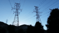
Five-hundred kilovolt (500 kV) Three-phase electric power Transmission Lines at Grand Coulee Dam.
-
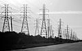
Three abreast Electrical Pylons in Webster, Texas.
-
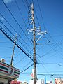
A 115 kV subtransmission line in the Philippines, with 20 kV distribution lines and a street light.
-
115 kV H-frame transmission tower.
-
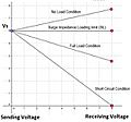
Voltage on sending and receiving ends for lossless line.
-
High voltage pylons carrying additional optical fibre cable in Kenya.


See also
 In Spanish: Transmisión de energía eléctrica para niños
