
Electric power distribution facts for kids

Electric power distribution is how electricity gets from where it's made to your home and other buildings. It uses things like power lines, transformers, and special stations called substations. Electricity starts at a power station at a very high voltage. It then travels through a system that lowers the voltage so it's safe and ready for you to use.
Long ago, electricity was sent as direct current (DC). But then, alternating current (AC) became popular during something called the War of Currents. AC won because transformers can easily change its voltage. This makes it simple to send electricity over long distances at high voltage and then lower it for everyday use.
Contents
How Electricity Reached Homes

People didn't need a big system to deliver electricity until the 1880s. Before that, electricity was usually made right where it was used. The first systems in cities delivered power for lights. There were bright arc lamps for streets and large spaces, and incandescent lights for homes and businesses. These new electric lights started to replace old gas lighting systems.
Arc lights used very high voltage, so one power station could light up a long string of lights, even 7-mile (11 km) away! But early home lighting systems, like Thomas Edison's first one in 1882, used low voltage (110 volts). This meant the power plants had to be very close to homes, usually within 1.5 miles (2.4 km). They also needed thick, expensive copper wires to carry the power.
The Amazing Transformer Arrives
Sending electricity long distances at high voltage and then lowering it for homes was a big challenge. But in the mid-1880s, a major breakthrough happened: the transformer was invented! Transformers could "step up" AC voltage for long-distance travel and then "step down" the voltage for users. This made sending electricity much cheaper. It also meant large power plants could supply whole cities, which saved a lot of money. Because of this, AC power quickly became very popular.
In the US, there was a famous "War of Currents" in the late 1880s. Thomas Edison, who liked DC, tried to scare people about AC. He pointed out accidents caused by high-voltage AC systems, saying they were too dangerous. But his campaign didn't last long. Even Edison's own company switched to AC by 1892.
AC became the main way to send power. New electric motors and "universal systems" helped connect old power systems to the new, large AC networks.
For a long time, one company often handled everything: making electricity, sending it, delivering it, and even billing customers. But starting in the 1970s, many countries began to change this. They allowed different companies to compete in making and selling electricity. However, the system that delivers power to your home usually stayed regulated.
From Power Plant to Your Town

Electricity starts at a power station. Here, the voltage can be as high as 13,800 volts. Most power stations use AC. Some places that need a lot of DC power, like certain railway electrification systems or factories that make aluminium, use special devices to change AC into DC. Sometimes, very high voltage DC (HVDC) is used to send power over extremely long distances or to connect different AC systems. For example, a long DC line sends power from the James Bay area in Canada all the way to Boston.
From the power station, electricity goes to a special yard. Here, a large transformer increases the voltage to a very high level, from 44,000 volts to 765,000 volts. This super-high voltage is perfect for sending electricity across the country. Once in this "transmission system," electricity from different power plants mixes together. Electricity is used the moment it's made, traveling almost at the speed of light!
How Electricity Spreads Out

The change from long-distance transmission to local distribution happens at a power substation. Substations do a few important jobs:
- They have special switches and Circuit breakers that can turn off parts of the power grid if needed.
- Transformers at the substation lower the super-high transmission voltages (like 35,000 volts or more) to "primary distribution voltages." These are medium-voltage circuits, usually between 600 and 35,000 volts.
- From the transformer, power goes to a main connection point called a busbar. This busbar splits the power into many different "distribution lines" that spread out to customers.
In cities, distribution lines are often underground. In the countryside, they are mostly above ground on utility poles. Suburban areas use a mix of both.
Closer to your home, a smaller "distribution transformer" lowers the primary distribution power even more. This creates a low-voltage "secondary circuit," which is usually 120/240 volts in the US for homes. The power then comes to your house through a "service drop" wire and an electricity meter. The final wire to a city home might be less than 50 feet long, but for a country home, it could be over 300 feet.
Primary Distribution: The Main Branches
Primary distribution voltages are usually between 4,000 and 35,000 volts. Only very large users, like big factories, get power directly at these voltages. Most homes and businesses are connected to a transformer that lowers this voltage to the "utilization voltage" or "mains voltage" used for lights and inside wiring.
How Networks Are Set Up

Distribution networks are either "radial" or "network" systems. A radial system is like a tree, where each customer gets power from just one source. A network system has many sources working together. Radial systems are common in rural or suburban areas.
Radial systems often have emergency connections. This means if there's a problem, like a fault or a need for repairs, the system can be reconnected to get power from a different path. This is done by opening and closing switches.
Long power lines can lose some voltage, so special devices called capacitors are sometimes added to help keep the voltage steady.
Power for Rural Areas
Rural electrification systems often use higher distribution voltages. This is because the power lines have to cover much longer distances in the countryside. For example, in the United States, 7,200, 12,470, 25,000, and 34,500-volt distribution is common. In the UK, Australia, and New Zealand, 11,000 and 33,000 volts are often used. Sometimes, rural areas only get "single-phase" power if it's too expensive to install "three-phase" power for just a few small customers.
Rural systems try to use fewer poles and wires. The cheapest way is with a "Single-wire earth return" (SWER) system, which uses just one wire. It uses higher voltages, which allows for stronger, cheaper steel wires and wider spacing between poles. In rural areas, one transformer on a pole might serve only one customer. Countries like New Zealand, Australia, Saskatchewan, Canada, and South Africa use SWER systems to bring electricity to remote areas.
Larger farms or water plants might need higher voltage or three-phase power. This costs more to set up but can make their equipment work better and save energy.
In some rural areas, a "4-wire" system is used, but to save on wires, the fourth "neutral" wire is connected to the ground. The ground then acts as the return path for the electricity.
Secondary Distribution: To Your Wall Outlet
Electricity is delivered at a frequency of either 50 or 60 Hertz, depending on where you live. For homes, it's usually delivered as single-phase electric power. In some countries, like in Europe, larger homes might get a three-phase supply. If you could see the power supply on a special device called an oscilloscope, it would look like a smooth sine wave. In North America, it goes between -170 volts and 170 volts, which gives an effective voltage of 120 volts. Three-phase power is more efficient for sending power and is better for running large electric motors. Some big European appliances, like electric stoves, might use three-phase power.
A ground connection is usually provided for your home's electrical system and for the utility company's equipment. This ground connection helps protect you if high-voltage wires fall onto lower-voltage wires, or if there's a problem inside a transformer.
How Voltages Differ Around the World

220-240 Volt Systems
Most of the world uses 50 Hertz and 220 or 230 volts for homes and small businesses. In these systems, the main distribution network sends power to a few substations in an area. From each substation, 230-volt power is sent directly to homes. Each home gets a "live" (hot) wire and a "neutral" wire. In Europe, electricity for homes and industries usually uses a three-phase, four-wire system. This provides 400 volts for three-phase power and 230 volts for single-phase power. In the UK, a typical substation for a neighborhood might be rated between 150,000 and 1,000,000 VA and supply hundreds of houses. Big industrial customers might get 690/400 volts three-phase, or they might even have their own transformers that take power directly from 11,000 to 220,000 volts.
110-120 Volt Systems
Most of the Americas use 60 Hertz AC. Homes use a 120/240 volt "split phase" system, and larger places use three-phase power. North American transformers usually send 240 volts to homes, similar to Europe's 230 volts. The "split-phase" system is what allows homes to use 120 volts.
In Japan, the standard frequencies are 50 and 60 Hertz. Some parts of the country use 50 Hertz, while others use 60 Hertz. This is because in the 1800s, some local power companies in Tokyo bought 50 Hertz equipment from Germany, while companies in Osaka bought 60 Hertz generators from the United States. The power grids grew until the whole country was wired. Today, Eastern Japan (including Tokyo) uses 50 Hertz, and Western Japan (including Osaka) uses 60 Hertz.
Most home appliances are made to work with either frequency. The difference became a big problem during the 2011 Tōhoku earthquake and tsunami. The earthquake knocked out about a third of the power in Eastern Japan. But power from Western Japan couldn't be fully shared with the East because the frequencies were different.
To help with this, Japan has four special stations called high-voltage direct current (HVDC) converter stations. These stations can change power between the 50 Hertz and 60 Hertz grids. They can move up to 1.2 billion watts of power between the East and West.
240 Volt Systems with 120 Volt Outlets
Most modern homes in North America are set up to receive 240 volts from the transformer. Thanks to "split-phase electrical power," these homes can have both 120-volt and 240-volt outlets. The 120-volt outlets are typically used for lighting and most wall outlets. The 240-volt outlets are usually for large appliances like electric ovens, water heaters, and clothes dryers. Sometimes, a 240-volt outlet is in the garage for tools or for charging an electric car.
Images for kids
-
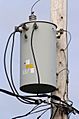
A 50,000 VA transformer mounted on a pole.
-
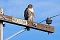
A power pole in rural Butte County, California.


See also
 In Spanish: Red de distribución de energía eléctrica para niños
