Type 271 radar facts for kids
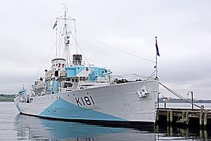
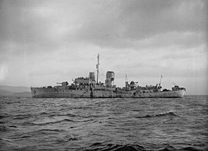
The Type 271 was the main radar for hunting submarines on HMCS Sackville. You can see its lighthouse-like dome above the ship's control room.
|
|
| Country of origin | UK |
|---|---|
| Manufacturer | Allen West and Co, Marconi |
| Designer | ASRE |
| Introduced | 1941 |
| Type | Sea-surface search, early warning |
| Frequency | 2950 ±50 MHz (S-band) |
| PRF | 500 pps |
| Beamwidth | 8.6º horizontal, 85º vertical |
| Pulsewidth | 1.5 µs |
| RPM | 2 rpm |
| Range | 1 to 11 NM (1.9–20.4 km) |
| Diameter | 28 in (0.71 m) |
| Azimuth | 220 to 360º |
| Precision | ~2º, 250 yards range |
| Power | 5 kW, 70 kW |
| Other Names | Type 272/3, CD Mk IV, V, VI, Chain Home Extra Low |
| Related | Type 277 radar, 276, 293 |
The Type 271 was a special radar used by the Royal Navy and its friends during World War II. It was the first widely used radar on ships that used microwave signals. This meant its antenna was small enough to fit on smaller ships like corvettes and frigates.
This radar was much better than older ones. It could spot a U-boat (German submarine) on the surface from about 3 miles (4.8 km) away. It could even see just the periscope of a submarine from 900 yards (820 m) away.
The first test version, called 271X, was put on HMS Orchis in March 1941. It was ready for use by May. More sets became available that year, with about thirty working by October. This design led to two bigger versions: Type 272 for destroyers and small cruisers, and Type 273 for larger cruisers and battleships. The Type 273 was very successful and used a lot.
Better versions, known as Q models or Mark IV, came out in early 1943. These had a stronger 70 kW magnetron for longer range. They also added a plan position indicator (PPI) display. This new screen made it much easier to find and track targets. Around the same time, new radar (ASV Mark III), signal detectors (huff-duff), and code-breaking (Naval Enigma) helped the Royal Navy. These changes turned the Battle of the Atlantic in favor of the Allies. Later that year, a Type 273Q radar on HMS Duke of York found the German battleship Scharnhorst at night. This led to its destruction during the Battle of the North Cape.
By the end of the war, even more improved versions came out. These were first called Mark V models. In March 1943, they were renamed Type 277, 276, and 293. These new models were put on ships when they came in for repairs. Type 271Q models stayed in use on some ships after the war.
Contents
- How Radar Changed Naval Warfare
- Early Radar and Big Antennas
- The Magnetron: A Game Changer
- Developing the Type 271 Radar
- The First Type 271X Models
- Testing the Type 271 at Sea
- Improvements: Type 271, 272, and 273
- The PPI Display: A New Way to See Targets
- New Radome Design
- Q Models: More Power and Better Performance
- Q Models in Action
- The 277 Series: Next Generation Radar
- Other Important Uses
- How the Type 271 Radar Worked
Early Radar and Big Antennas
The Royal Navy started looking into radar in 1935. Their Experimental Department quickly began making radars for ships. In 1938, their Type 79 radar was the first naval radar to be used.
Back then, powerful radio equipment used long wavelengths, measured in meters. This meant radar antennas had to be very large to work well. For example, the first Type 79X radar on HMS Saltburn in 1936 used a 4-meter wavelength. Its antennas were so big they had to be stretched between the ship's masts. The ship itself had to turn to aim the radar.
The Magnetron: A Game Changer
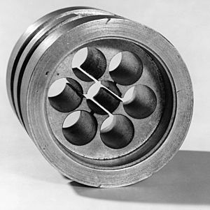
In February 1940, two scientists, John Randall and Harry Boot, built a working cavity magnetron. This small device, about the size of a shoebox, could produce 1 kW of power at a very short wavelength of only 10 cm.
This was a huge step forward! An antenna for this wavelength was only 5 centimetres (2.0 in) long. It could easily fit on almost any ship or aircraft. This invention started the development of microwave radar right away.
The Navy was in a good position to use the magnetron. Their Valve Laboratory helped create new electronic tubes for all of the UK's armed forces. By July 1940, more powerful magnetrons (5 to 10 kW) were ready. Scientists quickly put together the first working microwave radar on a table. They tested it by having someone ride a bicycle in front of it while holding a metal plate. This showed the radar could spot targets even very close to the ground or water.
Developing the Type 271 Radar
In 1940, the Battle of the Atlantic was going badly for the Royal Navy. German U-boats were sinking many ships. Most U-boat attacks happened at night, on the surface. This was because Asdic (sonar) could not detect surfaced submarines. Also, existing radars were too big for the small escort ships.
In September 1940, Winston Churchill, the Prime Minister, made developing an "efficient radar set for anti-submarine surface and air escorts" a top priority.
A team from the Admiralty Signal Establishment (ASE) went to study the new microwave radars. They developed their own version, called "Apparatus C." This was tested on December 8, 1940.
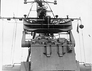
One challenge was that the radar beam needed to be narrow horizontally to be accurate. But it also needed to be wide vertically. This would help it stay on target as the ship moved up and down in the waves. Bernard Lovell suggested using a "cheese antenna." This antenna looked like a slice of cheese. It created a fan-shaped beam that spread over about 80 degrees vertically. This design helped the radar keep tracking targets even when the ship was rocking.
The First Type 271X Models
The Navy urgently ordered 12 prototype radar sets. These were called Type 271, and later 271X. To avoid signal loss, the main parts of the radar were placed right behind the antennas. This meant the operator's cabin had to be directly below the antenna.
The antenna was placed on a spinning platform. An operator turned it by hand using a steering wheel. To protect the radar from bad weather, a round dome was built around it. This dome was made of perspex, a clear plastic. It looked like a lighthouse lantern, which became its nickname.
Testing the Type 271 at Sea
In February 1941, the Navy ordered 100 production sets. The new Flower-class corvette HMS Orchis was chosen for sea trials. The radar was quickly installed on Orchis. Trials began in the Firth of Clyde on March 25, 1941.
The radar, mounted 36 foot (11 m) high, could track a small submarine from 4,000 yards (3,700 m). It even saw some targets as far as 5,000 yards (4,600 m). Even though this was less than expected, it was still very useful. It was much better than trying to see targets at night. The Navy decided to go ahead with this design for production.
By September 1941, 32 corvettes had the Type 271. A few other ships, like the battleship HMS King George V, also got it.
Improvements: Type 271, 272, and 273
During 1941, microwave electronics kept getting better. The new CV35 reflex klystron improved efficiency. This allowed the antenna to be up to 40 feet (12 m) away from the receiver. This gave ships more options for where to mount the radar. Sets using the CV35 were renamed Type 271 Mark II.
A new mounting system allowed the antenna to be turned remotely. This made the radar suitable for destroyers. In August 1941, units with this remote drive were renamed Type 272.
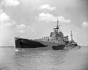
For larger ships, the "cheese antenna" was not ideal. These ships moved less in waves. So, engineers went back to using larger, 3 foot (0.91 m) diameter parabolic mirrors. These gave much better range. Six prototype systems were delivered in August 1941, called Type 273. The first Type 273 was fitted to HMS Nigeria at the end of the year.
The PPI Display: A New Way to See Targets
In 1941, the Air Ministry started working on the plan-position indicator, or PPI. This was a new type of radar display that showed a 2D map of the area around the radar. It's what most people think of when they imagine a radar screen. It has a round face with a line that sweeps around.
By late 1941, the Navy began adapting the PPI for the Type 271. This display made scanning the sea surface much easier. Operators could see the entire area at once. Before, they had to watch for small "blips" as they swung the antenna. Now, they could make one sweep and see everything.
In February 1942, an experimental PPI was put on the King George V. It proved to be very valuable. A contract was placed for production models.
New Radome Design
As more Type 271 radars were installed, operators noticed a problem. Reflections from larger ships in a convoy caused big areas of the display to become unusable. These were called "side echoes."
Tests in 1942 showed the problem was caused by the pillars supporting the roof of the "lantern" dome. A new design was created using thick, stacked cylinders of perspex. This new dome had no frame.
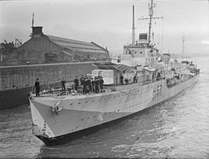
The first new dome was put on HMS Hesperus in November 1942. By the end of 1943, the entire fleet had been updated. The domes for the Type 273s took longer to design. They were heavier and had to withstand the blast from firing guns.
Q Models: More Power and Better Performance
By the end of 1941, new microwave technologies were ready. The "strapped" magnetron design was a big breakthrough. This small change greatly boosted performance. A magnetron the same size as the original could now produce 40% to 60% more power. This meant radars could now produce up to 500 kW of power!
The Navy wanted to use these new magnetrons quickly. They decided to keep the existing antennas but upgrade the transmitters. The new magnetrons were so powerful that they could damage the receiver's crystals. A special tube was added to protect the receiver from the strong signals.
The first tests were on HMS Marigold in May 1942. A second unit was fitted to the King George V in July. The increased power of the Q models made the side echoes even worse. This was solved by the new frameless radome.
Another problem was that close targets returned too much signal. This made it hard to see more distant targets, like U-boats near a convoy. This was fixed by a "swept-gain system" in late 1943. This system reduced the signals from close objects.
Q Models in Action
The Q models had about 45 times more power than the original Type 271. This increased their effective range by about 2.6 times. This was a big improvement. It allowed U-boats to be detected as far as the radar could "see" over the horizon. Also, signals from closer ranges were much stronger and more stable on the displays.
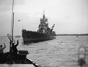
The Type 273Q's most famous moment was during the Battle of the North Cape on December 26, 1943. HMS Duke of York detected the German battleship Scharnhorst from 45,500 yards (41.6 km) away. The Duke of York was able to hit Scharnhorst with its first shots. This was because of the radar's early detection and accurate aiming. Scharnhorst didn't know Duke of York was there because its own radar was damaged.
During the battle, two shells from Scharnhorst hit the Duke of York's mast. This briefly knocked out the 273Q radar. Lieutenant Bates, the radar commander, climbed the mast and fixed the antenna. He became known as "Barehand Bates."
The Commander-in-Chief Home Fleet praised the radar's performance. He said the Type 273Q gave a clear picture of the battle. He also noted that the new cylindrical perspex dome greatly improved the radar by cutting down side echoes.
The radar also greatly improved the detection of submarines. From 1943, the average first sighting range increased from 3 to 5 miles (4.8 to 8.0 km). This was an increase of more than 50%.
The 277 Series: Next Generation Radar
Further improvements to the 271 series used the even more powerful CV76 magnetron. These new versions were first called Mark V. But they were so different that they were given new names: Type 277 radar, 276, and 293. These began replacing the 271s in mid-1944. By 1945, they were used for all new installations.
Some ships still received the 271Q during this time. For example, HMCS Haida got her 271Q in 1944. These later installations were often replaced after the war. Haida received a Type 293 in 1946.
Other Important Uses
The Type 271 radar was so advanced that it was used in other important roles during the war.
Coastal Defense Radar
The British Army used a version of the Type 271 for coastal defense. These radars were placed along the eastern coast of the British Isles. They looked for enemy ships in the English Channel. Older radars had trouble finding fast E-boats. The 271's shorter wavelength and better resolution solved this problem.
One of the first 271X units was sent to the Army's radar research site. For land use, the fan-shaped "cheese antenna" was not needed. It was replaced by a much larger parabolic reflector, 7 feet (2.1 m) in diameter. This greatly improved the radar's gain and range.
The whole system, including the operator's cabin, was put on an anti-aircraft gun carriage. The antennas were right next to the cabin and rotated with it. This kept the cables short. The first example was set up in July 1941. It was called Radar, Coast Defence, Number 1 Mark 4 (CD No.1 Mk.4).
Tests showed it was a huge improvement. It could reliably cover the Channel. Even E-boats could not pass between Calais and Boulogne without being detected. The Army immediately ordered more units.
Chain Home Extra Low: Spotting Low-Flying Planes
The Royal Air Force (RAF) noticed that German planes were flying very low to avoid their radars. These "tip-n-run" raids used fast fighter bombers like the Focke-Wulf FW 190. They flew only about 100 feet (30 m) over the water. They would bomb a target and quickly turn back. The planes were only visible to radar for a few moments.
To fight these attacks, the RAF took over eleven of the Army's CD units in December 1942. They renamed them AMES Type 52, but they were better known as Chain Home Extra Low. These radars followed the same improvements as the Army models. In total, 38 such stations were added to the network.
How the Type 271 Radar Worked
Antenna Design
The Type 271 needed a thin beam side-to-side for accuracy. But it also needed a wide beam up-and-down. This was so the signal would hit the water's surface even as the ship pitched and rolled. This led to the "cheese" antenna design. It looked like a slice cut from a parabolic reflector with plates on the top and bottom. This design squeezed the signal between the plates, making it spread out vertically.
The Type 271 was designed before a way to switch one antenna between transmitting and receiving was developed. So, it used two separate antennas, one on top of the other. The flat surfaces of the cheese antennas made this easy. The metal plates also protected the receiver from stray signals from the transmitter.
The antenna was mounted on a post. This post went through the roof of the radar operator's cabin. It ended in a large wheel that the operator used to turn the antenna by hand.
The standard antenna had a gain of about 55. The Type 273's larger 3 foot (0.91 m) reflector increased this to about 250. The land-based 273S model, with its 4.5 foot (1.4 m) reflector, improved it even more to 575.
Radar Electronics
The Type 271's electronics were very advanced for the 1940s. They show how hard it was to build such systems back then. The original 271X receiver had a lot of noise. But this improved in later production models. The use of US-made detector crystals helped even more.
In early versions, the equipment was in two large cabinets. These were about as tall as a refrigerator. For production units, this was reduced to a single cabinet. It had two large boxes at the bottom and middle, and a smaller unit on top. The bottom unit held the power supply. The middle unit had the receiver and display. The top unit had the tuner.
The P-models added the PPI display. The Q-models used the same layout as the P-models to make upgrades easier.
 | Toni Morrison |
 | Barack Obama |
 | Martin Luther King Jr. |
 | Ralph Bunche |


