Type 277 radar facts for kids
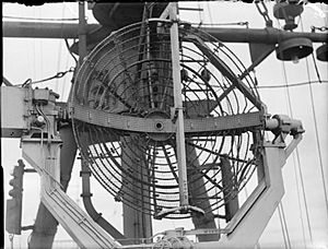
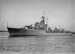
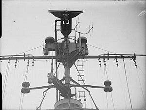
Type 277 antenna on HMS Swiftsure
|
|
| Country of origin | UK |
|---|---|
| Introduced | 1943 |
| Type | Sea-surface search, early warning |
| Frequency | 2950 ±50 MHz (S-band) |
| PRF | 500 Hz |
| Beamwidth | 6.2º |
| Pulsewidth | 1.8 or 0.7 µs |
| RPM | 0 to 16 rpm |
| Range | 1 to 11 NM (1.9–20.4 km) |
| Diameter | 4.5 ft (1.4 m) |
| Azimuth | 360º |
| Precision | ~2º, 250 yards range |
| Power | 500 kW |
| Other Names | Type 276, 293 |
| Related | Type 271/2/3, 294/5, 980 to 984, CD No.1 Mk. VI, AMES Type 50 to 56 |
The Type 277 was a special kind of radar used by the Royal Navy (Britain's navy) and its allies during World War II. It was designed to find ships on the surface of the sea and also to give early warnings about enemy aircraft.
This radar was a big upgrade from an older model called the Type 271 radar. The Type 277 was much more powerful and could process signals better. It also had new parts that helped it work much more effectively. Because it was so good, even smaller ships like corvettes could use a radar that was once only found on large cruisers and battleships. The Type 277 started being used in 1943 and became very common by the end of that year.
The older Type 271 radar was one of the first to use microwaves, which were a new technology back then. As the war went on, scientists learned a lot more about how to make microwave parts better. These improvements led to the creation of the Type 277.
The Type 277 used a powerful 500,000-watt magnetron (a special tube that creates microwaves). The older Type 271 only used a 5,000-watt magnetron. The new radar also had a much better antenna that could stay steady even when the ship moved. It used special cables called waveguides and had new screens called plan-position indicator (PPI) displays. These screens showed a map-like view of everything around the ship. While the Type 271 could only spot U-boats (enemy submarines) up to about 3 miles away, the Type 277 could see as far as the radar horizon (the farthest point the radar waves could reach).
The Type 277 led to other versions, like the Type 276 for destroyers and the Type 293 for finding aircraft. These radars were so strong that the British Army used them for watching the coast and helping aim artillery. The Royal Air Force (RAF) also used them to detect German planes flying very low. The radar continued to get better, with new models appearing in 1945. Some of these stayed in use until the 1950s.
Contents
- How Radar Technology Improved
- The First Microwave Radar: Type 271
- Making Radar Even Better: Q Models
- The Next Big Step: Mark V
- Testing New Ideas: The Prototype System
- New Names: Type 277T
- Testing the Naval Version: Type 277X
- Widespread Use: Type 277
- Radar for Destroyers: Type 276
- Radar for Aircraft Tracking: Type 293
- Even Better Antennas: Outfit AQR
- More Tests and Improvements
- The Final Models: P and Q
- Radars for Directing Fighters
- Other Uses of Type 277 Radar
- How the Type 277 Worked
How Radar Technology Improved
The First Microwave Radar: Type 271
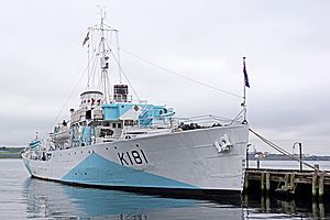
The Type 271 was one of the first radars to use microwave frequencies. It started being tested in March 1941 and was ready for use by May. At that time, microwave technology was very new. Even so, the Type 271 was very helpful. It was small enough for corvettes and could spot U-boats within about 3 miles.
The first Type 271 was made for small ships. Its antenna was placed right on top of the bridge. An operator would turn the antenna by hand using a steering wheel. The Type 272 was similar but used a cable to turn the antenna. It also had updated electronics to send data over longer distances. However, the Type 272 was not very successful.
The Type 273 was like the 272 but had a much larger antenna that looked like a dish. This dish helped it pick up signals better. Because this antenna had a narrow beam, it needed to be kept steady as the ship moved. A special gyroscope system helped keep it aimed at the horizon. This version worked very well and was used on larger ships like cruisers and battleships. The British Army also used unstabilized versions for coast defense.
Making Radar Even Better: Q Models
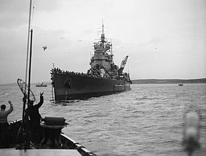
While the Type 271 was being installed, microwave electronics kept getting better. New parts from the United States helped receivers work with less electronic noise. The magnetron, which creates the radar's signal, also became much more powerful. These improvements meant radars could see much farther.
At the same time, the way signals were sent and received improved. Older coaxial cables were replaced with waveguides, which lost less signal. Antenna designs also got better. A key invention was the "soft Sutton tube," which allowed one antenna to both send and receive signals. New ways of processing signals also led to the first radar lock-on systems. These systems could automatically follow a target much more accurately than a human operator.
Some of these simpler improvements were put into a new design called the "Q" models (also known as Mark IV). These used more powerful magnetrons and new waveguide systems. After some testing, the first Q models were installed in May 1942. They mostly replaced the older models by late 1943.
The Next Big Step: Mark V
Even with the Q models, there was still a problem with the Type 272, which was supposed to let the radar be read from a distance. It was hard to mount, and the long distance to the electronics made it work poorly.
The soft Sutton tube, which allowed one antenna for sending and receiving, helped solve this. A lighter, single antenna meant a larger dish could be used. This would help make up for signal loss over long distances. Also, new rotating joints for waveguides meant that the old coaxial cables could be replaced. This allowed the antenna to spin all the way around (360 degrees) and greatly reduced signal loss.
Two new antenna designs were chosen. One used a 4.5-foot dish from the Army's coast defense radars. This larger dish could be mounted on a steady base even on small ships. This became the Type 271 Mark V. A second version, the Type 272 Mark V, kept the original "cheese-style" antenna but put it in a new case. This lighter antenna could be mounted on smaller masts. The new magnetron made it so powerful that it was expected to work as well as the larger Type 273Q.
Testing New Ideas: The Prototype System
The new magnetron was very powerful (500,000 watts), so it needed a strong power supply. To test the whole system, an experimental version called Type 273S Mark V was built in 1942. It had a large antenna (15 by 2.5 feet) on top of a cabin that could rotate. This was tested on the coast near RAF Ventnor.
At this time, the Navy was using the Type 281 radar for air warning on big ships. This radar was mounted low, so it couldn't see very far. It could only spot planes above 4,000 feet altitude at about 40 miles away. There was a strong need to "fill the gap" and see planes flying lower. People wondered if the new Mark V radars could do this.
To test this, the 273S was changed to include a separate IFF Mark III receiver. This allowed it to identify friendly aircraft. It was then moved to a test site in North Wales. Between December 1942 and February 1943, it showed it could detect a Bristol Beaufighter plane at 80 miles when it was flying at 8,000 feet. This was excellent performance.
New Names: Type 277T
In March 1943, the names of the radars were changed. The 271 and 272 Mark V models became the Type 277 and Type 276. The 273S Mark V was renamed 277T.
The 277T worked so well that the Army and Royal Air Force (RAF) ordered it for their use as Chain Home Extra Low (CHEL) radar. The first one was put into use in March 1943 at Capel-le-Ferne, Dover. It was very good at spotting German Focke-Wulf FW 190 planes that flew very low to attack. The 277T could see them soon after they left the French coast. It even helped warn of an attack on Ashford School in March 1943, saving students' lives.
The Type 277S (for Static, meaning it didn't move) had an even better mounting system. These started arriving in mid-1943. Some were sent to Europe during the D-Day landings.
While the 277T was being tested, work continued on the naval version of the antenna system, called 277X. The new 4.5-foot dish was made of metal mesh and mounted in a special "yoke" or "fork" mount. A motor on the mount helped keep it steady vertically. A gyroscope kept it level with the horizon. The radar could spin from 0 to 16 times per minute. It also had two screens: a PPI display and another to measure distance and height.
The 277X was tested on a ship called Saltburn. Even though the radar was mounted low on the ship, it worked very well. The new transmitter and improved antenna made the signal much stronger. During tests in April and May 1943, it could detect a medium bomber at 40 miles and find its height at 20 miles. The tests also showed that the stabilization system worked well, even in bad weather.
Widespread Use: Type 277
As the 277X tests continued, a new antenna made of wire mesh was introduced. This "Outfit AUK" worked just as well but was lighter and less affected by wind. Production of the Type 277 with the AUK antenna began in early 1943, and many ships had it by mid-1943.
Radar for Destroyers: Type 276
The idea behind the Type 276 was to use the original "cheese-style" antenna from the 271Q. This would make the radar smaller and lighter for mounting on a ship's mast. When combined with the new powerful magnetron from the 277 and a waveguide, it was expected to work as well as the larger 273Q radar. This made it a great replacement for the unsuccessful 272.
People also looked at how well it could detect aircraft. Its antenna was not as strong as the 277's, so it was expected to detect a light bomber at about 21 miles. It was noted that the "cheese" antenna might have trouble tracking planes at very high altitudes. A small change was made to the antenna to spread the beam out more vertically, helping it see higher planes.
Another small but important change was to replace the round cover with a flat sheet of clear plastic. This made it much easier to mount on a ship's mast. The first one was put on HMS Tuscan. In tests, the 276X could detect another ship at 29,000 yards (about 16.5 miles), which was just as good as the larger 273Q.
Radar for Aircraft Tracking: Type 293
During battles in the Mediterranean Sea, there were many air attacks. Anti-aircraft guns didn't always work well. The Navy wanted a radar that could constantly track aircraft at close range, especially when their position changed quickly. This new "Target Indication" (TI) radar was meant for destroyers and larger ships.
Tests with the 273Q radar on King George V for tracking aircraft weren't great. It was hard to track targets continuously and search for new ones at the same time. A PPI display, which showed all aircraft around the ship at once, was a big improvement. More tests were done with a PPI display on HMS Rother in July 1943.
The main problem was that the new dish antennas had very narrow beams. They weren't good for constantly scanning high angles, which the TI role needed. A fan-shaped beam, like the one from the original 271 or new 276 "cheese" antennas, would be better. A new antenna, Outfit AUR, was developed. It was wider but much shorter than the 276's. A system combining the 277's electronics with the AUR antenna was called the Type 293.
Larger ships could have both the dish-shaped AUJ for surface search and the AUR "cheese" for aircraft tracking. The electronics could switch between them. Smaller ships didn't need a TI radar. This left destroyers and small cruisers with a problem: they didn't have room for both. As aircraft tracking became more important, it was planned for the AUR to do both jobs. The mounting was designed so the 293 or 276 antennas could be easily swapped.
The first Type 293X was fitted to HMS Janus to test its performance in finding ships. It was tested in August and September 1943. The 293 could only detect another ship, Obedient, at 24,000 yards (about 13.6 miles). This was less than the 273Q and 276, meaning the 293 wasn't great for finding ships.
Even Better Antennas: Outfit AQR
Because the 293X didn't work very well for finding ships, the Navy rethought putting it on destroyers. The 276 was already in use and worked better against aircraft, though it struggled with planes above 8,000 feet.
This led to going back to the original 271Q "cheese" antenna for the 276. Instead of a full dome, a clear plastic plate covered the front of the "cheese." Many destroyers that had the 293 were later refitted with the 276.
All these tests showed that a radar that could do both aircraft tracking and surface search was possible. But the antenna needed to be much stronger. This led to a new antenna design, Outfit AQR. It was larger (8 feet wide and 7.5 inches high) and had a different design that made it lighter and less affected by wind. This antenna had much better signal gain than the 276's. When AQR models arrived in 1945, the older AUJ was replaced.
An even bigger version of the AQR, Outfit ANS, was developed for cruisers. It was called Type 293Q and could detect any aircraft at 18 miles, from the horizon up to 35,000 feet. It was very effective and stayed in service for many years after the war.
More Tests and Improvements
In March 1944, the 277 radar on the escort carrier HMS Campania was used to test against its own aircraft. Campania also had an older Type 281 radar. They used the 281 for tracking and the 277 for finding altitude. The 277 would be aimed at the target and then tilted up and down to find the best signal.
These tests showed how well the 277 could detect targets. For a plane flying at 2,000 feet, it could detect it 100% of the time up to 5 nautical miles, about 80% at 10 nautical miles, and almost zero at 40 nautical miles.
The Type 276 and 293 radars spun at a fixed speed. Campania tested different spinning speeds for the 277. It found that the detection ability didn't change much at slower speeds between 2.25 and 2.5 revolutions per minute.
Larger ships got the 277 first because its improved performance was very helpful for them. Later in 1944, the Navy learned that German U-boats were using a device called a Schnorkel to stay underwater longer. This made the 277 a top priority for smaller escort ships to help find these hidden submarines.
In September 1944, the corvette HMCS Copper Cliff got the AUJ antenna. It was mounted high on its mast, giving it a radar horizon of 9.5 miles. In tests, Copper Cliff could reliably detect a surfaced submarine at 11 miles. Against a Schnorkel, which was only 3 feet high, the range dropped to about 5.5 miles. Closer to the surface, it could get lost in the radar clutter from the waves.
The Final Models: P and Q
Even though the 277 was very advanced for 1943, by 1944, new improvements were available. These included better crystal detectors that could be connected directly to the waveguide. This made the system easier to tune. Also, new receivers reduced the system's electronic noise.
New anti-jamming systems were also added. These could filter out wide-band signals if the radar was being jammed by the enemy. The radar's control panels were also redesigned to make them easier to use and maintain. These changes led to the 277P and 293P models.
These new models were ready by mid-1945. However, by late 1944, many major fleet ships were being prepared to move to the Pacific Ocean. To get these ships equipped quickly, a special project called "Project Bubbly" was started. The battleship HMS Anson received the first unit in March 1945.
Because air attacks were a big part of the Pacific war, there was a desire to make the 277 and 293 even better. For the "Fighter Direction" role (commanding aircraft operations over a wide area), even the 277P didn't have enough range. A new 8-foot diameter antenna was designed. To reduce clutter from waves, this radar used vertical polarization, which scattered less from the water.
The final system, Type 277Q, arrived too late for Project Bubbly and was used after the war. In tests in March 1947, the 277Q could reliably detect targets for aircraft tracking up to 85 miles and find their height up to 55 miles. These were huge improvements. The system was very effective and stayed in service for many years.
Radars for Directing Fighters
Battles in the Mediterranean showed that fighter aircraft needed to be better coordinated to fight German and Italian air forces. In 1942, experiments were done with a special display for the Type 281 radar that showed a map-like view. This display worked well, but the 281 wasn't very clear and got confused by land.
Tests of the 277T in late 1942 were very promising. Later that year, the Navy asked for a special radar just for Fighter Direction (FD). This radar needed to detect any aircraft above 35,000 feet up to 80 miles away. It also needed to find their height very accurately. This would require a large, heavy, and very stable antenna. So, only aircraft carriers and special Fighter Direction Ships would carry it.
Early calculations showed that a "cheese-type" antenna 12 feet wide could provide the same signal strength as the 277's dish. But the radar needed to double its range. To do this, plans were made to use a magnetron that was four times more powerful (2 million watts) and had a longer pulse length.
Since the radar needed to find height while still scanning, a separate height-finding system was needed. A second antenna would be placed above the main "cheese" antenna. This would create multiple vertical "lobes" (areas where the radar signal was strong) to help find height. This new system was called Type 295. An interim Type 294 would use the existing Type 277 magnetron if the new one wasn't ready. By 1944, it was clear the height-finding system wasn't working, so both plans were put on hold.
New requirements were issued for separate PPI (map display) and height-finder radars using Type 277 magnetrons. These became the Type 980 and 291. They also had problems but eventually entered service as Type 982 and Type 983.
Other Uses of Type 277 Radar
The Navy's work on large magnetron-based radars was ahead of the Air Force and Army during the war. Because of this, many land-based radars used by both forces later in the war were based on Navy equipment. The Type 277 was one of these.
Coast Defense Radar: CD Mark VI
When the 277T radar showed excellent results, the British Army adopted it almost unchanged. They called it Radar, Coast Defence, Number 1, Mark VI (CD No. 1 Mk. VI). CD radars were used to spot ships in the English Channel. Earlier CD radars were less accurate, but with the 277, they could even pick out individual German E-boats leaving the French coast.
Air Ministry Radar: AMES Type 50
When the Army started using its first Coast Defense radars, the Air Ministry took some of them. They placed them on high towers to see low-flying aircraft. These became the Chain Home Low systems. They could detect planes as low as 500 feet at ranges that allowed fighter planes to intercept them. These were officially called AMES Type 2.
When the Army upgraded its CD radars to the 271P, the RAF did the same, calling them AMES Type 30. When they moved to the 277, they became Type 50. These systems were generally known as Chain Home Extra Low (CHEL).
The AMES Type 50 was almost the same as the 277T, using a "cheese" reflector. The Type 52 used parabolic dishes for even better performance. This led to a series of designs (Types 52 to 56) that only differed in how they were mounted. To make it confusing, any of these might be called CHEL. Often, CHEL and CD were the same system, just called by different names depending on whether the Army or Air Force was talking about it.
RAF Height Finders: AMES Type 13 and 14
In 1941, the Royal Air Force (RAF) started using a new land-based radar called AMES Type 7. It became clear that the Type 7 wasn't great at measuring height. A need for a dedicated height finder was developed, which became the AMES Type 13. Since the 277T tests were so successful, it was chosen as the basis for the Type 13.
The main difference was the antenna. For height finding, the radar beam needs to be narrow vertically and wide horizontally. The Type 13 used a huge "cheese" antenna, 20 feet high and 18 inches wide. It was so big it had to be built in two connected parts.
As the Type 13 began production, the RAF worried that Germans would use "Window" (strips of metal foil) to block their radars. So, production of the Type 13 was changed to the Type 14. This was basically a Type 13 turned on its side, making it scan the horizon like the CD and CHEL radars. This produced a PPI display.
When they went back to the Type 13, its performance was disappointing. Existing units were used as PPI units by turning off the "nodding" system and rotating them manually. Improvements were made, but the system wasn't truly good until the Mark V, which came after the war. The Mark V used a new antenna. When combined with a Type 14, the two-unit system was called a Type 21.
How the Type 277 Worked
This section describes the main parts of the Type 277 radar.
Antenna Design
The standard antenna for the Type 277 was a wire-mesh parabolic dish, about 4.5 feet across. The radar signal traveled to and from the antenna through a waveguide. This waveguide ran vertically across the front of the dish, holding it firmly in place. This design gave the system a strong signal gain of 800. Later, the 277Q used an even stronger dish (gain of 1750), while the smaller 276 had a lower gain (180).
The antenna was mounted in a "fork mount." A motor on one side of the fork helped keep the antenna steady vertically. A special rotating joint for the waveguide was on the other side. This joint allowed the signal to travel from the radar cabin to the antenna as it spun.
Electronic Parts
The Type 277's electronics were very advanced for 1944. They had many new systems that made them better than the Type 271. For example, new detector crystals from the US made the receiver much quieter, meaning it could pick up weaker signals.
The entire radar system was built into a single cabinet. It had two large sections at the bottom and middle, and a smaller unit on top. The bottom section held the power supply. The middle section had the receiver and the display screens. The top section held the tuning controls.
 | Leon Lynch |
 | Milton P. Webster |
 | Ferdinand Smith |


