
Lunar Roving Vehicle facts for kids
Quick facts for kids Lunar Roving Vehicle |
|
|---|---|

|
|
| Overview | |
| Manufacturer | |
| Also called |
|
| Designer |
|
| Powertrain | |
| Electric motor | Four .25-horsepower (0.19 kW) series-wound DC motors |
| Transmission | Four 80:1 harmonic drives |
| Battery | Two silver-oxide, 121 A·h |
| Range | 57 miles (92 km) |
| Dimensions | |
| Wheelbase | 7.5 ft (2.3 m) |
| Length | 10 ft (3.0 m) |
| Height | 3.6 feet (1.1 m) |
| Weight |
|
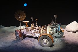
The Lunar Roving Vehicle (or LRV) was a special electric car used by astronauts on the Moon. It had four wheels and was powered by batteries. Astronauts used it during the last three Apollo missions (Apollo 15, 16, and 17) in 1971 and 1972. People often called it the Moon buggy because it looked a bit like a "dune buggy" you might see on Earth.
The LRV was built by a company called Boeing. Each one weighed about 462 pounds (210 kg) (without any cargo). It could carry up to 970 pounds (440 kg), which included two astronauts, their tools, and Moon rocks they collected. The LRV was designed to go up to 6 miles per hour (9.7 km/h), but on its last trip during Apollo 17, it actually reached a top speed of 11.2 miles per hour (18.0 km/h)!
Each LRV was folded up and packed inside the Lunar Module for the trip to the Moon. Once on the Moon, astronauts unpacked it. Each LRV traveled about 30 kilometres (19 mi) on average, and they worked very well. All three LRVs used in the Apollo missions are still on the Moon today.
Contents
What is the Lunar Roving Vehicle?

The Apollo Lunar Roving Vehicle was an electric car made to work in the Moon's low gravity and empty space. It helped Apollo astronauts travel much farther from their landing spot. This meant they could explore more of the Moon's surface.
Three LRVs were used on the Moon:
- The first was on Apollo 15 by astronauts David Scott and Jim Irwin.
- The second was on Apollo 16 by John Young and Charles Duke.
- The third was on Apollo 17 by Eugene Cernan and Harrison Schmitt.
On each mission, the mission commander was always the driver. They sat in the left seat of the LRV.
How Big and Heavy Was It?
The Lunar Roving Vehicles weighed about 460 pounds (210 kg) on Earth. They were built to carry an extra 510 pounds (230 kg) of payload. Because the Moon's gravity is much weaker (about one-sixth of Earth's), the LRV felt much lighter there. An empty LRV weighed about 77 pounds-force (35 kgf) on the Moon, and a fully loaded one weighed about 160 pounds-force (73 kgf).
The LRV frame was 10 feet (3.0 m) long, and its wheels were 7.5 feet (2.3 m) apart (this is called the wheelbase). The vehicle stood about 3.6 feet (1.1 m) tall. The frame was made of strong 2219 aluminium alloy tubing. It had three parts that could fold in the middle. This allowed it to be folded up and stored in a special bay of the Lunar Module.
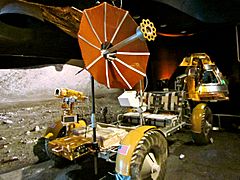
The LRV had two foldable seats made of aluminum tubes with nylon webbing. There were also aluminum floor panels. An armrest was placed between the seats, and each seat had adjustable footrests and a Velcro seat belt to keep the astronauts safe. A large mesh antenna was on a pole at the front of the rover. This antenna helped with communication. When fully loaded, the LRV was about 14 inches (36 cm) off the ground.
Wheels and Power

The wheels were designed by General Motors. Ferenc Pavlics was specially recognized by NASA for creating these unique "resilient wheels." Each wheel had a hub made of spun aluminum. The tire was 32-inch (81 cm) wide and 9-inch (23 cm) in diameter. It was made of zinc-coated steel strands woven together. To help with grip on the Moon's dusty surface, titanium chevron shapes covered half of the tire's surface. Inside the tire, there was a titanium frame to protect the hub. Dust guards were placed above the wheels to keep dust away.
Each wheel had its own electric motor, made by Delco. Each motor could produce 0.25 horsepower (190 W) of power. This power was sent to the wheel through a special gear system. Each wheel also had its own brake. If a motor stopped working, astronauts could disconnect it, allowing the wheel to spin freely.
The LRV could steer using both its front and rear wheels. Each steering motor produced 0.1 horsepower (75 W) of power. The front and rear wheels could turn in opposite directions, allowing the LRV to make very tight turns (with a turning radius of 10 feet (3 m)). The wheels were linked in a way that helped prevent the rover from sliding sideways when turning.
Power came from two 36-volt batteries. These were special silver-zinc batteries that could not be recharged. Each battery had enough power for 121 A·h, giving the LRV a total range of 57 miles (92 km). These batteries powered the drive and steering motors. They also had a 36-volt outlet at the front to power the communication system or the TV camera. The LRV's batteries and electronics were cooled using special wax packages and shiny surfaces that faced upwards. While driving, these cooling surfaces were covered to prevent dust buildup. When the LRV stopped, astronauts would open the covers and brush off any dust to help with cooling.
How Astronauts Controlled the Rover


Astronauts controlled the LRV with a T-shaped handle placed between the two seats. This handle controlled the four drive motors, the two steering motors, and the brakes.
- Pushing the stick forward made the LRV go forward.
- Moving it left or right turned the vehicle.
- Pulling it backward activated the brakes.
- To go in reverse, an astronaut would flip a switch on the handle before pulling it back.
- Pulling the handle all the way back put on the parking brake.
In front of the handle, there were screens that showed important information. These included the LRV's speed, direction, how steep the ground was, and the power and temperature levels.
To navigate, the LRV kept track of its direction and distance using a special compass (a directional gyro) and a distance counter (an odometer). This information was sent to a computer that always knew the LRV's overall direction and how far it was from the Lunar Module. There was also a tool that used the Sun's shadow to help astronauts figure out their direction, since the Sun moves very slowly in the Moon's sky.
How the LRV Was Used
The LRV was used during the Moon walks of Apollo 15, 16, and 17. These were called the "J missions" of the Apollo program. On each mission, the LRV was used for three separate Moon walks, making a total of nine trips across the lunar surface. The mission commander always drove the LRV, while the Lunar Module Pilot was a passenger who helped with navigation.
| Mission | Total distance traveled | Total time spent driving | Longest single trip | Farthest distance from the LM |
|---|---|---|---|---|
| Apollo 15 (LRV-1) | 17.25 miles (27.76 km) | 3 hours 02 minutes | 7.75 miles (12.47 km) | 3.1 miles (5.0 km) |
| Apollo 16 (LRV-2) | 16.50 miles (26.55 km) | 3 hours 26 minutes | 7.20 miles (11.59 km) | 2.8 miles (4.5 km) |
| Apollo 17 (LRV-3) | 22.30 miles (35.89 km) | 4 hours 26 minutes | 12.50 miles (20.12 km) | 4.7 miles (7.6 km) |
There was a rule for using the LRV: astronauts had to be able to walk back to the Lunar Module if the LRV ever broke down. This was called the "Walkback Limit." So, the trips were planned so that astronauts could always walk back safely. They would drive to the farthest point first, then work their way back towards the Lunar Module. This way, as their oxygen and supplies ran low, the distance they had to walk back also got shorter. This rule was made a bit more flexible during the longest trip on Apollo 17, because the LRV and spacesuits had proven to be very reliable on earlier missions.
How the LRV Was Unpacked

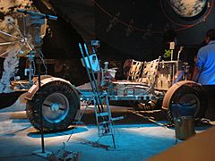
Unpacking the Lunar Roving Vehicle from the Lunar Module's bay was done using a system of pulleys, ropes, and special tapes. The rover was folded up and stored in the bay with its underside facing out.
One astronaut would climb down the ladder from the Lunar Module. The other astronaut on the ground would slowly tilt the rover out using the ropes and reels. As the rover was lowered, most of it unfolded automatically. The rear wheels folded out and locked into place. When they touched the ground, the front of the rover could be unfolded, its wheels deployed, and the whole frame lowered to the surface using pulleys.
Once unfolded, all the rover's parts locked into their correct positions. Then, astronauts would remove cables, pins, and tripods. They would raise the seats and footrests. After turning on all the electronics, the LRV was ready to drive away from the Lunar Module.
Where Are the LRVs Now?
Four LRVs were built for space flight. Many others were made for testing and training. Three of the flight-ready LRVs were taken to the Moon on the Apollo 15, 16, and 17 missions (LRV-1 to LRV-3). They were left there. The fourth LRV (LRV-4) was kept for spare parts after the Apollo 18 mission was canceled.
The LRV used on Apollo 15 was left at a place called Hadley-Apennine (26°06′N 3°39′E / 26.10°N 3.65°E). The LRV from Apollo 16 was left at Descartes (8°59′S 15°31′E / 8.99°S 15.51°E). The LRV from Apollo 17 was left at Taurus-Littrow (20°10′N 30°46′E / 20.16°N 30.76°E). This last rover was even seen by the Lunar Reconnaissance Orbiter spacecraft in 2009 and 2011. In 2020, the state of Washington officially recognized these rovers on the Moon as historic landmarks.
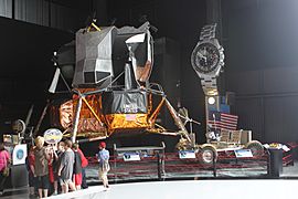
Since only the top part of the Lunar Module could fly back to orbit from the Moon's surface, the LRVs and the lower parts of the Lunar Modules were left behind. This means the only lunar rovers you can see on display are LRV-4, test vehicles, training models, and mock-ups.
Here are some places where you can see these LRV models:
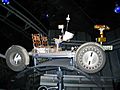
- Lunar Roving Vehicle 4 (LRV-4) is at the Kennedy Space Center Visitors Complex in Cape Canaveral, Florida.
- The Engineering Mockup, used to design the rover, is at the Museum of Flight in Seattle, Washington.
- The Qualification Test Unit, used to test all the rover's systems together, is at the National Air and Space Museum in Washington, D.C..
- The Vibration Test Unit, used to test how well the rover could handle the shaking of a rocket launch, is at the Davidson Saturn V Center at the U.S. Space & Rocket Center in Huntsville, Alabama.
- The 1-gravity trainer, used for practice on Earth, is at the Johnson Space Center in Houston, Texas.
Many other test units were built, like a static model and models for practicing in low gravity.
- Lunar Roving Vehicles, test vehicles and trainers
-
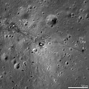
LRO image of Apollo 15 site, LRV-1 is near the right edge
-
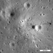
LRO image of Apollo 16 site, LRV-2 is near the right edge
-
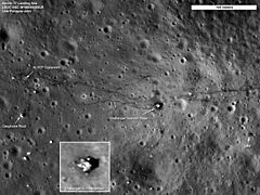
LRO image of Apollo 17 site, LRV-3 is in the lower right
-
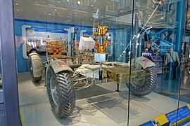
LRV-4, KSC Visitors Complex
-
LRV 1-gravity trainer, Space Center Houston
-
LRV engineering mockup, Museum of Flight
-
LRV Vibration Test Unit, U.S. Space & Rocket Center
-
LRV Qualification Test Unit, National Air and Space Museum
.jpg)


.jpg)
.jpg)


You can also find replicas (copies) of the rovers at many museums and visitor centers, including the Johnson Space Center in Houston, Texas, the Kennedy Space Center Visitors Complex in Cape Canaveral, Florida, the National Museum of Naval Aviation in Pensacola, Florida, the Evergreen Aviation & Space Museum in McMinnville, Oregon, the Kansas Cosmosphere and Space Center in Hutchinson, Kansas, and the Omega Museum in Biel, Switzerland. A replica is also on display at the Mission: Space attraction at Epcot in Walt Disney World Resort near Orlando, Florida.
Images for kids
-
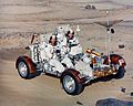
Apollo 16 astronauts in the 1-g trainer
-
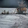
John Young works at the LRV near the LM Orion on Apollo 16 in April 1972.
-
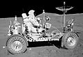
Apollo 15 – Commander David Scott drives the Rover near the LM Falcon
-

Lunar rover on Space Achievement Decade Issue of 1971
-
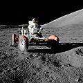
Eugene Cernan test drives the Apollo 17 lunar rover shortly after unloading it from the LM Challenger
-
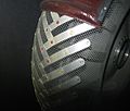
Close-up of wheel showing chevron treads
-
Rover replica on display at Epcot


See also
 In Spanish: Lunar Roving Vehicle para niños
- List of artificial objects on the Moon
- Lunar Terrain Vehicle
- Modular Equipment Transporter
