Synchrotron facts for kids
A synchrotron is a special type of particle accelerator. It makes tiny particles, like electrons or protons, travel very fast in a big circle. Imagine a race track for super-tiny particles! It uses strong magnets to keep the particles in a circle. It also uses electric fields to make them go faster and faster. Everything is carefully timed to work with the fast-moving particles. Scientists like Mark Oliphant, Vladimir Veksler, and Edwin McMillan helped invent and build the first synchrotrons.
Contents
How Synchrotrons Work
A synchrotron is an improved version of an older machine called a cyclotron. In a cyclotron, particles move in a spiral shape. It uses a steady magnetic field and a steady electric field.
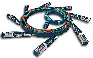
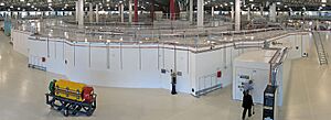
A synchrotron is different. Both the magnetic and electric fields change as the particles speed up. This change keeps the particles moving in a perfect circle, not a spiral. Because the path is a circle, the machine can be built as a large, thin, circular pipe. This pipe is called a torus. It often has straight sections between the curved parts.
These straight sections are important. They hold special equipment. This includes parts that add energy to the particles. They also hold devices like wigglers and undulators. These devices can pull out energy from the particles. Most synchrotrons use two main types of magnets. Dipole magnets bend the particle beam. Quadrupole magnets keep the beam focused and narrow.
The faster particles go, the more energy they have. The maximum energy a machine can give particles depends on the strength of its magnets. It also depends on how tight the circle is. To get more energy, scientists build bigger machines. These machines have stronger magnets and larger circles.
Older cyclotrons had a limit to their size. Their entire path had to be a single, disc-shaped vacuum chamber. This made them hard to build very large. Also, the strength of their magnets was limited.
Synchrotrons solve these problems. They use a narrow pipe for the particles. This pipe can be surrounded by many smaller, stronger magnets. However, there's another challenge. When charged particles speed up in a circle, they give off light. This is called synchrotron radiation. This radiation makes the particles lose energy.
The particles can only get so much energy. This limit is reached when the energy they lose from turning equals the energy they gain. To get more power, synchrotrons are built with very large circles. They also use more powerful microwave cavities to speed up the particles. Lighter particles, like electrons, lose more energy when they turn. So, the energy of electron accelerators is limited by this light loss. For heavier particles like protons, this loss is not as big a problem. Their energy is mostly limited by the strength of the magnets and the cost of the machine.
How Synchrotrons are Designed and Operated
Particles are first injected into the main synchrotron ring. They already have a lot of energy. This energy comes from a smaller machine. It might be a linear accelerator (linac) or another, smaller synchrotron. The linac itself gets particles from a simple high-voltage power supply.
Operators carefully calculate the magnetic field needed. This field guides the particles onto the synchrotron's path. They then send enough electricity to the electromagnets to create this field.
Once the particles are in, the magnetic field is slowly increased. The particles pass through an electric accelerator. This accelerator uses a high-voltage, changing electric field. As particles get faster, the frequency of this electric field changes. This keeps them speeding up. When particles get close to the speed of light, the frequency stays almost the same. But the current in the bending magnets keeps increasing.
The maximum energy particles can reach depends on the magnets. It's limited by how much magnetic field the magnets can produce. One way to get more power is to make the circular path even bigger. This allows for more bending magnets. Another way is to use superconducting magnets. These magnets can create much stronger fields.
When the particles reach their top speed, they are guided out of the synchrotron. They are then aimed at a target. Early synchrotrons used a fixed target. But in the 1970s, scientists found a way to get even more energy. They started colliding two beams of particles. These beams travel in opposite directions. To do this, they use particles with the same mass but opposite charges. For example, electrons and positrons, or protons and antiprotons.
Large Synchrotrons Around the World
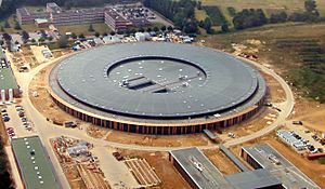
One of the first big synchrotrons was the Bevatron. It was built in 1950 in the United States. This machine could accelerate protons to 6.3 GeV (billion electron volts). Many new elements, not found naturally, were first made using the Bevatron.
Another early large synchrotron was the Cosmotron. It was built in 1953 and reached 3.3 GeV. The first synchrotron at Cornell University was built before 1950. It reached 300 MeV.
Until 2008, the Tevatron in the United States was the most powerful synchrotron. It accelerated protons and antiprotons to almost 1 TeV. It then collided them together. The Large Hadron Collider (LHC) is now the most powerful. It is located at CERN in Switzerland. The LHC is about seven times more powerful than the Tevatron. It can collide protons at about 14 TeV. It is built in a 27 km (17 mile) long tunnel. This tunnel used to house another particle collider. The LHC is one of the largest scientific machines ever built. It can also accelerate heavy particles like lead.
A huge synchrotron called the Superconducting Super Collider (SSC) was planned in Texas. It would have used superconducting magnets. These magnets create very strong magnetic fields. Its planned circle was 87.1 kilometers (54.1 miles) long. It aimed for 20 TeV per beam of protons. Construction started in 1991 but was stopped in 1994.
While proton accelerators can still get more powerful, electron accelerators face a challenge. They lose too much energy from synchrotron radiation. So, the next step for electron beams might be linear accelerators. These would be much longer than current ones. Scientists are working on the International Linear Collider (ILC). It will have two opposing linear accelerators. One for electrons and one for positrons. They will collide at a total energy of 0.5 TeV.
However, synchrotron radiation is also very useful. It has many applications. Many modern synchrotrons are built specifically to create and use this light. The largest of these are the European Synchrotron Radiation Facility (ESRF) in France. Also, the Advanced Photon Source (APS) in the USA, and SPring-8 in Japan. They accelerate electrons to 6, 7, and 8 GeV, respectively.
Large synchrotrons are very expensive to build. They cost hundreds of millions of dollars. Each research station, called a beamline, costs millions more. Governments and groups of countries usually fund these facilities. They are used by scientists from universities and research centers worldwide. Smaller, more compact synchrotrons are also being developed. One example is the Compact Light Source.
List of Synchrotron Facilities
| Synchrotron | Location & Country | Energy (GeV) | Circumference (m) | Commissioned | Decommissioned |
|---|---|---|---|---|---|
| Advanced Photon Source (APS) | Argonne National Laboratory, USA | 7.0 | 1104 | 1995 | |
| ALBA | Cerdanyola del Vallès near Barcelona, Spain | 3 | 270 | 2010 | |
| Tantalus | Madison, Wisconsin, USA | .2 | 9.38 | 1968 | 1995 |
| ISIS | Rutherford Appleton Laboratory, UK | 0.8 | 163 | 1985 | |
| Australian Synchrotron | Melbourne, Australia | 3 | 216 | 2006 | |
| ANKA | Karlsruhe Institute of Technology, Germany | 2.5 | 110.4 | 2000 | |
| LNLS | Campinas, Brazil | 1.37 | 93.2 | 1997 | |
| SESAME | Allaan, Jordan | 2.5 | 125 | Under Design | |
| Bevatron | Lawrence Berkeley Laboratory, USA | 6 | 114 | 1954 | 1993 |
| Birmingham synchrotron | University of Birmingham, UK | 1 | - | 1953 | |
| Advanced Light Source | Lawrence Berkeley Laboratory, USA | 1.9 | 196.8 | 1993 | |
| Cosmotron | Brookhaven National Laboratory, USA | 3 | 72 | 1953 | 1968 |
| National Synchrotron Light Source | Brookhaven National Laboratory, USA | 2.8 | 170 | 1982 | |
| Nimrod | Rutherford Appleton Laboratory, UK | 7 | 1957 | 1978 | |
| Alternating Gradient Synchrotron (AGS) | Brookhaven National Laboratory, USA | 33 | 800 | 1960 | |
| Stanford Synchrotron Radiation Lightsource | SLAC National Accelerator Laboratory, USA | 3 | 234 | 1973 | |
| Synchrotron Radiation Center (SRC) | Madison, USA | 1 | 121 | 1987 | |
| Cornell High Energy Synchrotron Source (CHESS) | Cornell University, USA | 5.5 | 768 | 1979 | |
| Soleil | Paris, France | 3 | 354 | 2006 | |
| Shanghai Synchrotron Radiation Facility (SSRF) | Shanghai, China | 3.5 | 432 | 2007 | |
| Proton Synchrotron | CERN, Switzerland | 28 | 628.3 | 1959 | |
| Tevatron | Fermi National Accelerator Laboratory, USA | 1000 | 6300 | 1983 | 2011 |
| Swiss Light Source | Paul Scherrer Institute, Switzerland | 2.8 | 288 | 2001 | |
| Large Hadron Collider (LHC) | CERN, Switzerland | 7000 | 26659 | 2008 | |
| BESSY II | Helmholtz-Zentrum Berlin in Berlin, Germany | 1.7 | 240 | 1998 | |
| European Synchrotron Radiation Facility (ESRF) | Grenoble, France | 6 | 844 | 1992 | |
| MAX-I | MAX-lab, Sweden | 0.55 | 30 | 1986 | |
| MAX-II | MAX-lab, Sweden | 1.5 | 90 | 1997 | |
| MAX-III | MAX-lab, Sweden | 0.7 | 36 | 2008 | |
| ELETTRA | Trieste, Italy | 2-2.4 | 260 | 1993 | |
| Synchrotron Radiation Source | Daresbury Laboratory, UK | 2 | 96 | 1980 | 2008 |
| ASTRID | Aarhus University, Denmark | 0.58 | 40 | 1991 | |
| Diamond Light Source | Oxfordshire, UK | 3 | 561.6 | 2006 | |
| DORIS III | DESY, Germany | 4.5 | 289 | 1980 | |
| PETRA II | DESY, Germany | 12 | 2304 | 1995 | 2007 |
| PETRA III | DESY, Germany | 6.5 | 2304 | 2009 | |
| Canadian Light Source | University of Saskatchewan, Canada | 2.9 | 171 | 2002 | |
| SPring-8 | RIKEN, Japan | 8 | 1436 | 1997 | |
| KEK | Tsukuba, Japan | 12 | 3016 | ||
| National Synchrotron Radiation Research Center | Hsinchu Science Park, Taiwan | 3.3 | 518.4 | 2008 | |
| Synchrotron Light Research Institute (SLRI) | Nakhon Ratchasima, Thailand | 1.2 | 81.4 | 2004 | |
| Indus 1 | Raja Ramanna Centre for Advanced Technology, Indore, India | 0.45 | 18.96 | 1999 | |
| Indus 2 | Raja Ramanna Centre for Advanced Technology, Indore, India | 2.5 | 36 | 2005 | |
| Synchrophasotron | JINR, Dubna, Russia | 10 | 180 | 1957 | 2005 |
| U-70 synchrotron | Institute for High Energy Physics, Protvino, Russia | 70 | 1967 | ||
| CAMD | LSU, Louisiana, US | 1.5 | - | - | |
| PLS | PAL, Pohang, Korea | 2.5 | 280.56 | 1994 |
- Note: For colliders, the energy listed is for one beam. If two beams collide head-on, the total energy is double the energy shown.
What Synchrotrons are Used For
Synchrotrons are used in many different fields of science and technology. Here are some examples:
- Life sciences: Studying proteins and large molecules to understand how they are built. This is called crystallography.
- Making tiny parts: Used in a process called LIGA for microfabrication.
- Drug research: Helping to discover and develop new medicines.
- Computer chips: Used to "burn" designs onto metal wafers for computer chips.
- Chemical analysis: Analyzing chemicals to find out what they are made of. This is done using spectroscopy and X-ray crystallography.
- Cell studies: Watching how living cells react to different drugs.
- Material science: Studying the structure of inorganic materials and semiconductors.
- Fluorescence studies: Looking at how materials glow under certain light.
- Geology: Analyzing geological materials like rocks and minerals.
- Medical imaging: Creating detailed images inside the body.
- Cancer treatment: Using proton therapy to treat some types of cancer.
Images for kids
-
The first synchrotron to use the "racetrack" design with straight sections, a 300 MeV electron synchrotron at University of Michigan in 1949. It was designed by Dick Crane.
See also
 In Spanish: Sincrotrón para niños
 | Chris Smalls |
 | Fred Hampton |
 | Ralph Abernathy |


